A Radio over IP gateway can be online, reachable and passing audio while the overall communication path still performs poorly. In field deployments, the more difficult problems are usually not whether the gateway can connect, but where delay is being introduced, why PTT response changes between sites, or why audio becomes unstable only when the WAN is busy.
These faults are easier to solve when the RoIP system is treated as a series of measurable sections instead of one end-to-end black box. Radio keying, gateway processing, packet transport, VPN handling, jitter buffering and the remote RF path can each contribute their own delay or failure point.
For deployment work, the useful question is therefore not simply whether the gateway is configured correctly. It is whether each section of the communication chain has been measured, verified and documented.
1. Map the RoIP Path Before Changing Parameters
Before changing codec settings, PTT delays or QoS policies, draw the actual communication path used by the project. Include the radio equipment and network devices between the two endpoints.
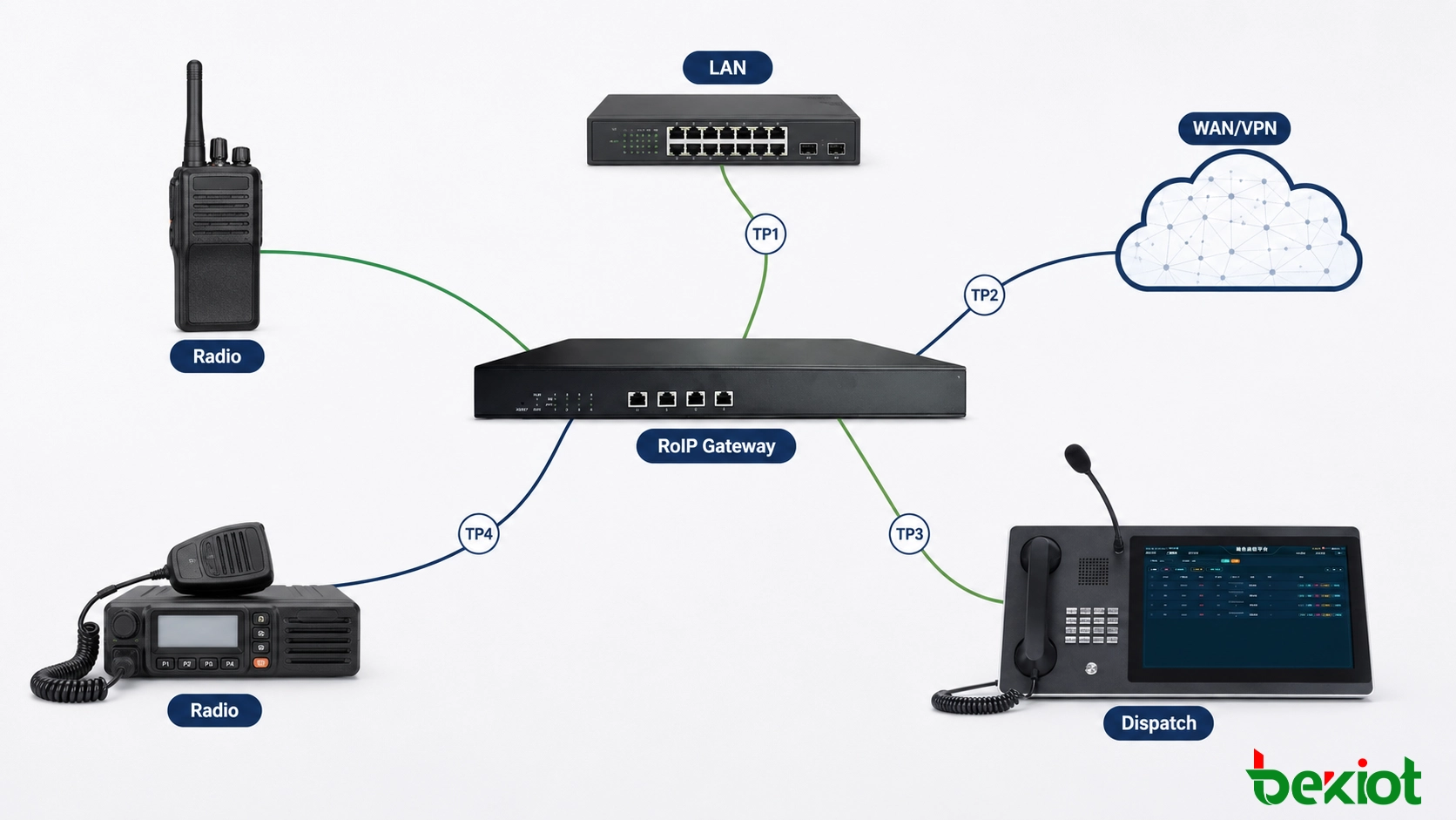
A typical multi-site path may be:
Radio → RoIP Gateway → LAN Switch → Router → VPN/WAN → Router → Dispatch Platform or Remote Gateway → Radio
The exact topology may be more complicated. A remote site may use fiber as the primary connection and 4G/5G as backup. A control center may place the RoIP platform behind a firewall. Some projects also separate radio traffic into a dedicated VLAN or route it through a corporate VPN.
What matters during commissioning is knowing where one section ends and the next begins.
Useful test points normally include:
radio receive audio entering the gateway;
gateway transmit audio entering the radio;
PTT output from the gateway;
radio transmit activation;
IP media leaving the local gateway;
IP media arriving at the remote endpoint;
remote gateway audio output;
and the final RF transmission heard by the receiving radio.
This map becomes the basis for every later test. If an operator reports delayed or broken audio, the engineer can check each section separately instead of changing several unrelated parameters at the same time.
Related RoIP Solution: Radio Over IP Gateway System
2. Build a Latency Budget for the Complete Radio Path
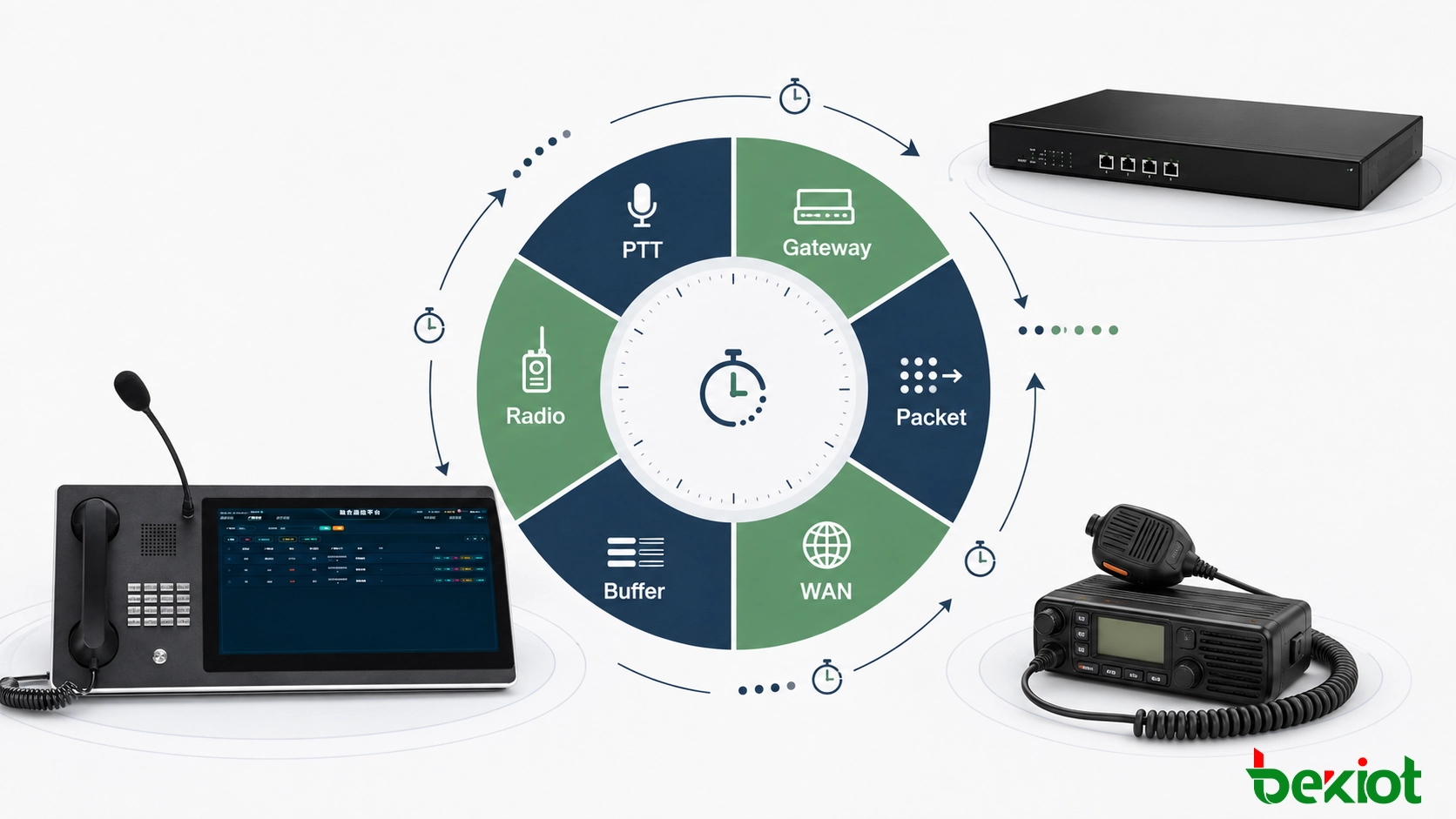
A single ping result does not describe RoIP response time. Ping mainly shows network reachability and IP round-trip delay. The radio operator experiences a longer chain that begins when PTT is requested and ends when useful speech reaches the remote radio.
For troubleshooting, break the total delay into separate components:
Total RoIP Response = PTT Processing + Local Gateway Processing + Packetization + IP Transport + Jitter Buffer + Remote Processing + Radio Key-Up + RF System Delay
The exact contribution of each component depends on the equipment and network. The purpose of a latency budget is not to force every project into one fixed number. It is to identify where the delay is actually being added.
Separate network delay from radio delay
Suppose the WAN path is stable but users still report that PTT feels slow. Reducing network latency may not solve the problem if most of the delay is coming from radio key-up time or a large jitter buffer.
The opposite can also happen. Radio keying may be fast at both sites, but a heavily loaded WAN or VPN path introduces variable delay between the gateways.
These two faults require different corrective actions, which is why total delay should be separated into measurable sections.
Measure the same path under different conditions
Record latency with the network idle, then repeat the same test during normal business traffic. If possible, test again while the WAN is intentionally placed under controlled load.
A useful comparison is:
idle network latency;
normal production latency;
peak-load latency;
and backup-link latency, if a secondary WAN is used.
A link that is acceptable when idle but becomes inconsistent during production traffic usually points to a network capacity, queuing or path-quality issue rather than a radio interface problem.
3. Measure PTT-to-Audio Timing Instead of Guessing
PTT timing is often adjusted by trial and error. A more reliable method is to measure several events in sequence and identify exactly where useful audio begins.
For example:
T0: remote PTT command is issued;
T1: gateway PTT output changes state;
T2: connected radio enters transmit mode;
T3: RF carrier is available;
T4: useful speech begins on the RF channel.
The difference between these points provides much more useful information than simply describing the system as having “high PTT latency.”
If the delay between T0 and T1 is excessive, investigate control signaling or gateway processing. If T1 occurs quickly but T2 or T3 is slow, the radio equipment or radio interface should be checked. If the RF carrier is already established but speech arrives late, investigate the audio path and media buffering.
Use the actual radio when setting lead time
PTT lead time should be matched to the connected radio or repeater. Different equipment can require different intervals between PTT activation and useful audio.
A value copied from another project may appear to work but still produce clipped speech or unnecessary delay.
The same principle applies to release timing. If PTT is released before the final audio leaves the radio, the last syllable may be cut off. If it is held too long, the channel remains occupied after speech has ended.
The goal is not the shortest possible delay. The goal is the shortest timing that still produces complete and repeatable transmissions with the actual radio equipment.
4. Verify QoS Under Congestion, Not from Configuration Screens
QoS should be proven by traffic behavior rather than assumed from a configuration page.
A gateway may mark real-time traffic correctly while an intermediate switch, firewall, VPN device or WAN service changes or ignores that marking. The configuration can therefore look correct at both endpoints while RoIP traffic still competes with bulk data during congestion.
A practical test is to observe the RoIP path under controlled load.
The test can be performed in stages:
Establish a normal radio call and record latency, jitter and packet loss.
Introduce background traffic on the same WAN path.
Repeat PTT and audio tests.
Check whether packet markings remain unchanged along the route.
Inspect router or firewall queues where congestion occurs.
Compare the result with the idle-network baseline.
If the RoIP path remains stable while background traffic increases, the network policy is doing its job. If speech begins to break up or latency varies sharply, investigate available bandwidth and queue behavior before changing gateway audio or radio settings.
QoS cannot replace sufficient bandwidth
Priority handling helps real-time traffic during contention, but it does not create capacity that does not exist. A WAN link that is permanently saturated still needs a bandwidth or traffic-engineering solution.
This is especially important in networks where RoIP shares the same connection with CCTV, file synchronization, office applications or other high-volume services.
Check backup links separately
If a project uses 4G/5G or another secondary connection, do not assume that the QoS behavior of the primary WAN also applies to the backup path.
The backup route may have different latency, jitter, packet-loss characteristics or traffic policies. It should therefore be measured as a separate communication path.
5. Locate the Fault by Segment
Changing several gateway parameters at once makes troubleshooting harder because the original fault disappears into the configuration changes. A better method is to isolate the path and determine which section first shows the problem.
| Observed Condition | Likely Area to Check |
|---|---|
| Local radio audio is good, but remote IP audio is poor | Gateway input level, packetization, codec path or IP network |
| IP media arrives correctly, but RF audio is distorted | Gateway output level, radio input level or radio modulation |
| Audio is clear, but PTT response is slow | PTT signaling, gateway control timing or radio key-up |
| System works when idle but fails during busy periods | WAN capacity, congestion, QoS or VPN performance |
| Only one direction has audio | Media routing, firewall, audio wiring or directional configuration |
| Problem appears only after WAN failover | Backup routing, NAT, VPN recovery, QoS or alternate-path quality |
| First part of speech is consistently missing | PTT-to-audio timing and radio transmitter key-up |
Use known-good sections to narrow the search
If local radio-to-gateway audio has already been verified, do not repeatedly adjust that interface while investigating a WAN problem. Keep each verified section unchanged and move to the next test point.
The same method works in the opposite direction. If RTP or other IP media reaches the remote gateway without packet loss but the RF output is poor, network tuning is unlikely to correct the problem.
Segment-based testing is particularly useful in multi-site systems because the same gateway model may work correctly at several locations while one site behaves differently. Comparing measurement points between a good site and a bad site can quickly identify whether the difference is in the radio interface, WAN path or local network.
6. Record a Deployment Baseline Before Handover
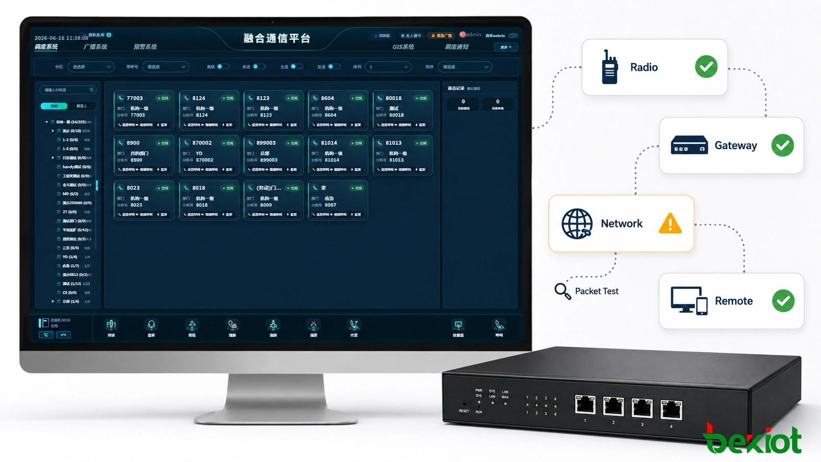
A RoIP system is easier to maintain when the final working values are recorded before handover. Without a baseline, a later router replacement, radio change or software upgrade can leave technicians unsure whether the current parameters are original or have already been modified.
The deployment record should contain the values that are useful for comparison, not every page of the equipment configuration.
| Category | Recommended Baseline Information |
|---|---|
| Radio Interface | TX level, RX level, interface type and relevant radio settings |
| PTT | PTT method, lead time, release time and measured response |
| Audio Transport | Codec, packetization and media destination |
| Buffering | Jitter-buffer configuration where applicable |
| Network | Gateway IP, VLAN, subnet, route and WAN path |
| Security | VPN path, firewall policy and required communication rules |
| QoS | Traffic marking and the network devices expected to preserve it |
| Measurements | Latency, jitter, packet loss and PTT-to-audio timing |
| Failover | Backup route, recovery behavior and measured backup-path performance |
Measurements should be recorded from the actual production path rather than copied from a laboratory configuration. Where possible, keep both the normal operating values and the results recorded during busy-network or failover testing.
This baseline becomes useful whenever a component changes. If a new router increases latency, a replacement radio requires a different PTT lead time, or a new WAN service introduces higher jitter, the maintenance team has an earlier working condition for comparison.
A Radio over IP gateway deployment is therefore not finished when the devices show an online status. It is finished when the communication path has been measured section by section, PTT timing has been verified with the real radio equipment, network behavior has been tested under load, and the final working values have been recorded for future troubleshooting.