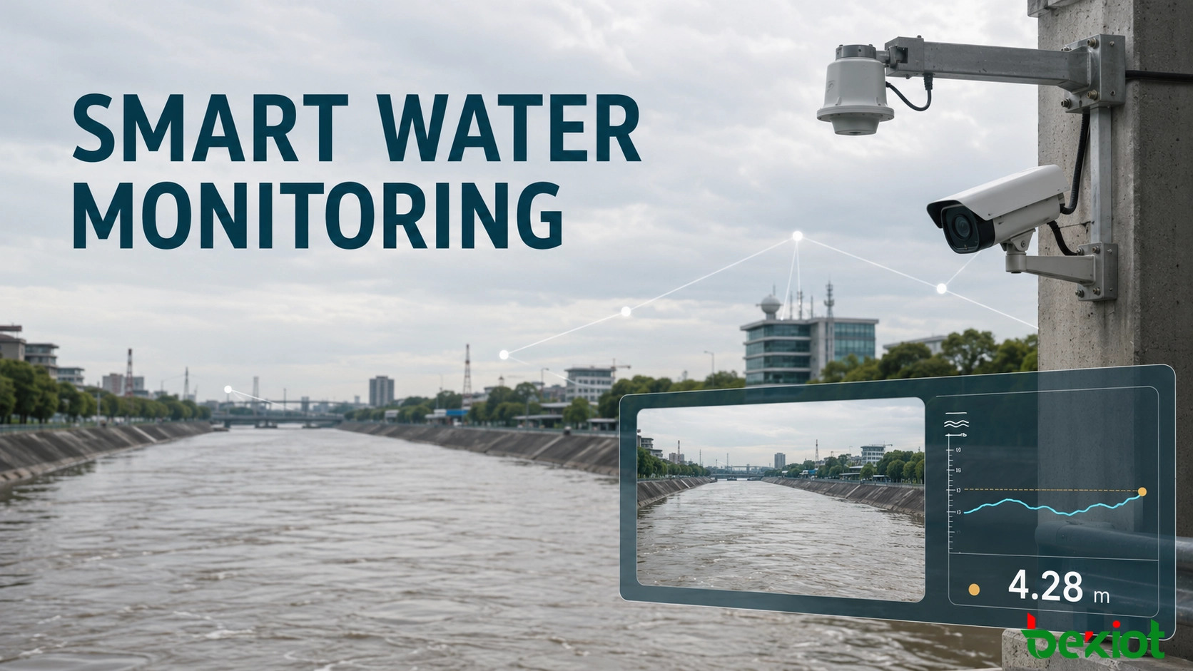
A water-level value tells operators what is happening, while live video helps them understand why it is happening. In a smart water monitoring project, placing both on the same screen gives control-room teams a faster way to verify abnormal readings, inspect surrounding conditions and decide whether an alert requires immediate action. A practical architecture uses a radar sensor for measurement, an existing camera for visual context and a video integration platform to synchronize the two sources. This avoids asking one device to perform every task and allows organizations to upgrade monitoring without replacing a serviceable CCTV network.
Why measurements and images should appear together
Hydrological telemetry and video surveillance are often built as separate systems. The telemetry page shows the latest level, while the CCTV platform shows the river, reservoir, gate or drainage channel. When an alarm occurs, an operator must switch applications, locate the correct camera and compare two timelines. That delay is small during routine work but important during heavy rain, rapid level changes or a developing flood event.
A synchronized overlay places the current water-level value, measurement time and status directly on the relevant live stream. The image can reveal floating debris, an obstructed channel, surface turbulence, a damaged structure or maintenance activity that a number alone cannot explain. The sensor value, meanwhile, provides a repeatable measurement that does not depend on an operator estimating a staff-gauge reading from a compressed image.
The objective is not to decorate a video with extra text. It is to create one operational view in which measurement, visual confirmation and incident handling share the same site identity and time reference. The same model can also display flow velocity, discharge and rainfall when those data sources are available.
The displayed quantity must also be defined precisely. Water depth, stage and elevation are related but are not interchangeable. A project should identify the reference datum, engineering unit, sensor offset and rounding rule before the value reaches the screen. Where operations depend on rapidly changing conditions, the view can include the rate of rise and a short trend indicator as separate calculated fields. These calculations should retain their source interval and quality status so that an operator can distinguish a confirmed trend from a result produced by incomplete samples.
Select the right source for the level reading
When video analytics are appropriate
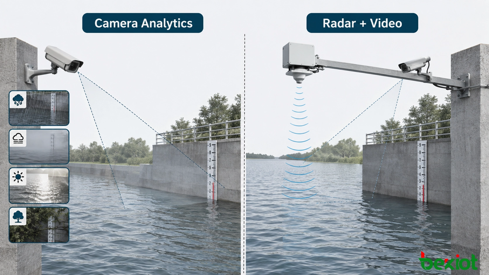
A camera can estimate water level by locating a staff gauge, waterline or other calibrated reference in the image. This approach naturally combines the scene and calculated result. It can be useful at sites with a stable viewpoint, controlled lighting, a visible reference and a well-tested image-analysis model.
The constraints need to be evaluated carefully. Rain, fog, glare, darkness, spray, vegetation, debris and lens contamination can hide the reference or alter image quality. A narrow channel or irregular terrain may prevent the camera from achieving the required angle. Reliable interpretation may also require significant processing, model tuning and site-specific validation. These weaknesses matter most during severe weather, precisely when dependable readings are most valuable.
Why non-contact radar is often the primary instrument
A radar level sensor measures the distance between its mounting position and the water surface, then converts that distance into a level referenced to the site datum. Because it is non-contact, the sensor is not submerged and is less exposed to fouling or damage from sediment and floating debris. It is also less dependent on daylight and visual clarity than camera-only measurement, making it suitable for continuous monitoring at rivers, reservoirs, canals and urban drainage sites.
Radar is not a substitute for good engineering. Mounting geometry, the measurement footprint, bridge vibration, obstructions, waves, turbulence, reference-datum accuracy, power and communications can all affect results. Each installation still needs a survey, commissioning checks and periodic comparison with an approved reference. Its practical limitation in this solution is different: the instrument normally supplies a data value rather than a visual explanation of conditions at the site.
| Decision factor | Camera-based measurement | Radar plus contextual video |
|---|---|---|
| Primary result | Calculated level and scene from one image source | Independent level measurement with a synchronized scene |
| Dependence on visibility | High; image quality and reference visibility are critical | Level measurement is less dependent on lighting and visibility |
| Site geometry | Requires a stable, suitable view of the measurement reference | Sensor and camera positions can be optimized separately |
| Processing needs | Image analysis, calibration and site-specific validation | Telemetry normalization, source mapping and video overlay |
| Use of existing CCTV | May require repositioning or a dedicated measurement camera | Ordinary cameras can often remain as visual evidence sources |
Build a synchronized data-and-video path
The integration layer sits between field devices and the applications used by operators. It receives the radar reading through the available telemetry network and ingests the corresponding camera stream. A site map links each sensor to one or more cameras so that the correct value is never shown on the wrong scene.
Acquire the measurement. Collect the water level together with its source ID, timestamp, engineering unit and quality or communications status.
Normalize the data. Convert field messages into a consistent internal format while retaining the original value and source time.
Ingest the live camera. Connect to the existing camera, recorder or video-management system through a supported interface.
Bind the sources. Maintain an explicit relationship among the monitoring site, sensor, camera, datum and alarm rules.
Compose the operator view. Add a readable overlay containing the value, unit, timestamp and data-quality state without obscuring critical parts of the image.
Distribute and record. Deliver the combined view to authorized applications while preserving the original sensor records and, where required, the unmodified video.
Data provenance should remain visible throughout this path. A normalized record should retain the original device identifier, source timestamp, receive timestamp, unit, quality code and conversion rule. If field communications are intermittent, the edge gateway may buffer measurements and forward them after recovery, but delayed records must be marked as historical rather than presented as live. This prevents network delay from being mistaken for a sudden change in the river or reservoir.
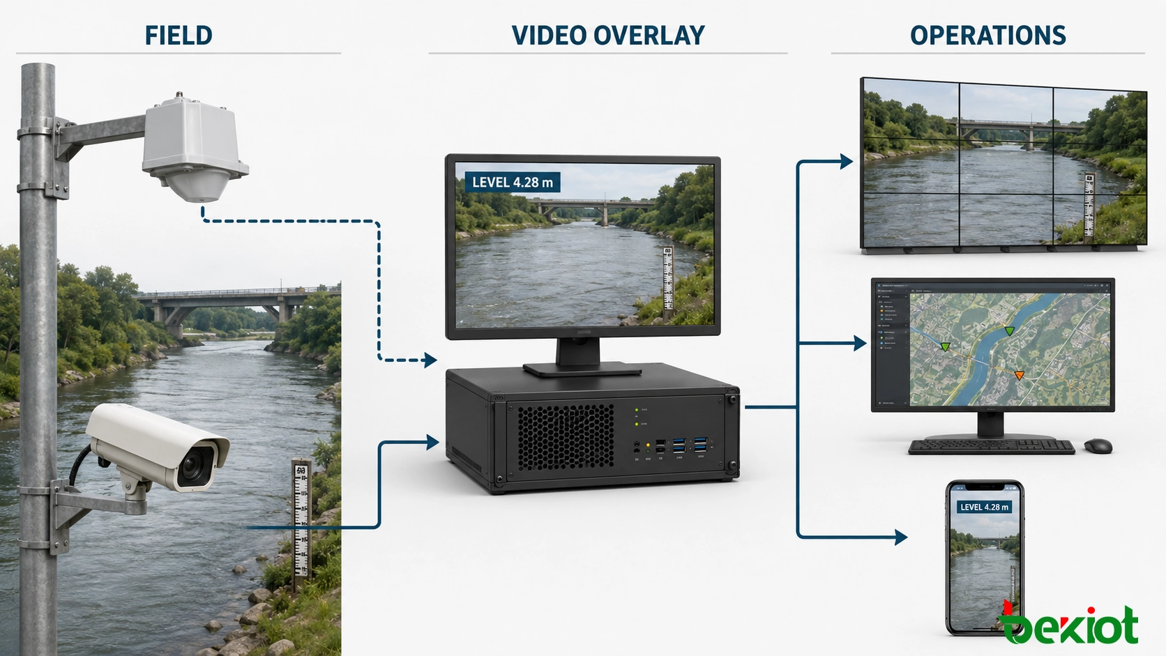
The output method should match the destination. RTSP is commonly used to set up and control real-time media delivery, while WebRTC is appropriate when low-latency browser viewing and interaction are required. RTMP, HLS and HTTP-FLV may support contribution or web distribution in suitable environments. SIP can provide session and signalling integration with compatible communications or dispatch systems. Protocol support alone does not guarantee interoperability; codec, authentication, latency, encryption, browser and firewall requirements must also be tested.
Video processing capacity should be sized from concurrent streams, resolution, frame rate, codec and the need for transcoding. Passing through a compatible stream generally consumes fewer resources and introduces less delay than decoding and encoding it again. Adaptive substreams can serve mobile users while the high-quality source remains available for evidence and control-room display.
This architecture can feed a control-room video wall, a GIS-based “one map” interface, a dispatch console, a browser dashboard or a mobile application. Reusing installed cameras reduces field work and protects earlier CCTV investment, while measurement accuracy remains the responsibility of the dedicated hydrological sensor and its installation.
Turn a screen value into an incident workflow
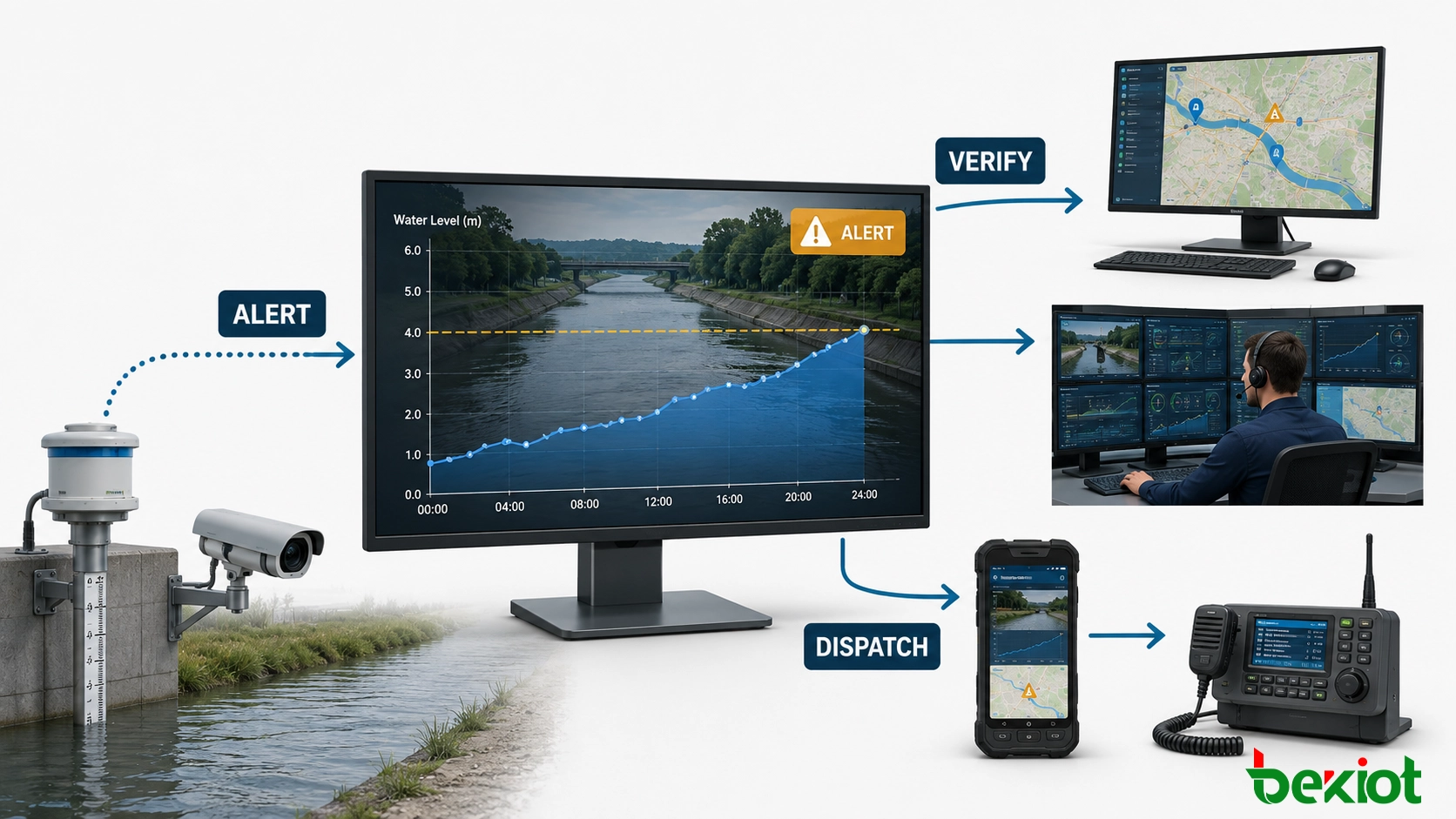
The greatest operational gain comes from linking the overlay to alarm handling. Instead of asking staff to watch every channel continuously, the platform evaluates configured thresholds and presents the relevant scene when a condition is met. Warning and critical levels should be based on the approved site plan, with hysteresis or persistence rules to prevent repeated alarms when the water surface moves around a boundary.
A typical event can open the associated camera, emphasize the current reading, start an incident record and notify the duty team. Depending on the surrounding systems, notifications may be delivered through the control-room desktop, mobile application, telephone workflow or radio-dispatch interface. Escalation rules can route an unacknowledged alarm to another role. All actions should be logged so that managers can reconstruct when the value changed, what operators saw and how the response progressed.
More reliable decisions can be produced by combining conditions without hiding the original measurements. A high-level threshold may create a warning, while a continuing rate of rise, upstream rainfall or a second monitoring point raises its priority. Operators should be able to see which condition triggered the event and which rule changed its severity.
The displayed status must distinguish a current measurement from a stale one. If the telemetry link fails, the last known value should not continue to appear as though it were live. A clear “data unavailable” or “last update” state is safer than a visually convincing but outdated number. The video and sensor channels should also fail independently: losing the camera must not erase telemetry, and losing telemetry must not stop the original video service.
Plan commissioning around evidence, not appearance
A successful demonstration is not enough. The deployed system must prove that the displayed number belongs to the correct sensor, represents the correct datum and remains aligned with the video during normal operation and network interruptions. Before handover, the project team should verify the following items:
Site identity: sensor IDs, camera IDs and map locations match the approved asset register.
Reference datum: the radar mounting reference and displayed elevation or depth use the unit and datum expected by operators.
Time synchronization: gateways, sensors, recorders and application servers use a controlled time source and preserve source timestamps.
Measurement quality: readings are checked against an accepted reference across representative water conditions.
Video usability: the view shows the relevant channel, bank, gate or structure by day and night without the overlay covering essential evidence.
Alarm behavior: threshold, persistence, acknowledgement, escalation and recovery rules produce the intended operational response.
Network performance: bandwidth, end-to-end delay, packet loss and reconnect behavior are tested under realistic loading.
Evidence retention: original measurements, source video, derived streams, alarm records and operator actions follow the organization’s retention policy.
Access control: viewing, configuration, acknowledgement and export permissions are separated according to job role.
Maintenance: cleaning, inspection, datum checks, configuration backup and fault-response responsibilities are documented.
Availability and cybersecurity should be treated as operating requirements. Sensor gateways, cameras and servers should use separate credentials, least-privilege accounts and controlled network zones. Remote administration should be encrypted and logged. For critical sites, redundant power, store-and-forward telemetry and a secondary processing node can maintain essential services. Recovery tests should confirm reconnection and the accuracy of data accumulated during the interruption.
The final design should keep raw sources available wherever auditability matters. A composed video is excellent for rapid understanding, but it should not become the only record. Retaining source telemetry and original video makes it possible to investigate timing differences, correct an overlay configuration and reproduce an event without altering the evidence.
Frequently asked questions
How should sensor and video timestamps be aligned?
Use a common network time source, store timestamps in UTC and retain the time reported by the field device whenever it is available. The platform should define an acceptable offset and flag sources that exceed it. Synchronization should be tested after restarts and communication outages, not only during initial setup.
Does adding an overlay change the original recording?
It does not have to. A robust design keeps the original camera stream or recording and creates a separate derived view, or stores the overlay information as associated metadata. This protects evidential integrity while still giving operators a convenient combined display.
What should happen when a sensor stops updating?
The value should enter a stale or unavailable state after a defined interval. The screen should show the last-update time, change the visual status and create a communications or device-health alert. The last valid reading must not be presented as a current measurement.
Can one level sensor be associated with several cameras?
Yes. A wide view, a close view and a downstream view may all provide useful context for the same measurement point. The configuration should identify one primary scene and label every additional view clearly so operators understand the relationship.
Which records are useful for post-event review?
Keep the raw telemetry series, device-quality states, original video, combined incident clip, alarm transitions, notifications, acknowledgements and configuration-change history. Together, these records show both the physical event and the system’s operational response.