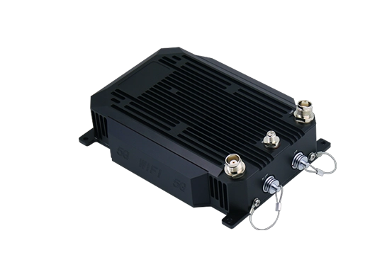

Two PAGA systems can provide almost identical paging and general alarm functions while using very different physical architectures.
In one project, controllers, amplifiers and interface equipment may all be installed in a central communication room. In another, control remains centralized but amplification is distributed across several process areas, buildings or remote stations.
The choice affects much more than equipment placement. It influences speaker cable length, network dependency, fault isolation, equipment-room requirements, maintenance access and future expansion.
For a compact facility, centralized amplification may be the simplest solution. As a site becomes larger or more geographically dispersed, distributed or hybrid architecture often becomes more practical.
PAGA SystemsRelated solution:
1. What Does PAGA Systems Architecture Define?
PAGA systems architecture defines how control, audio routing, amplification and field speaker circuits are arranged across a facility.
A simplified audio path can be represented as:
Paging or alarm source → PAGA controller → audio routing → amplifier → speaker circuit → loudspeakers
The main architectural question is where these functions should be located.
A centralized design keeps most active equipment in one location and distributes amplified audio to the field. A distributed design moves selected functions, especially amplification, closer to the areas they serve. A hybrid design combines both approaches.
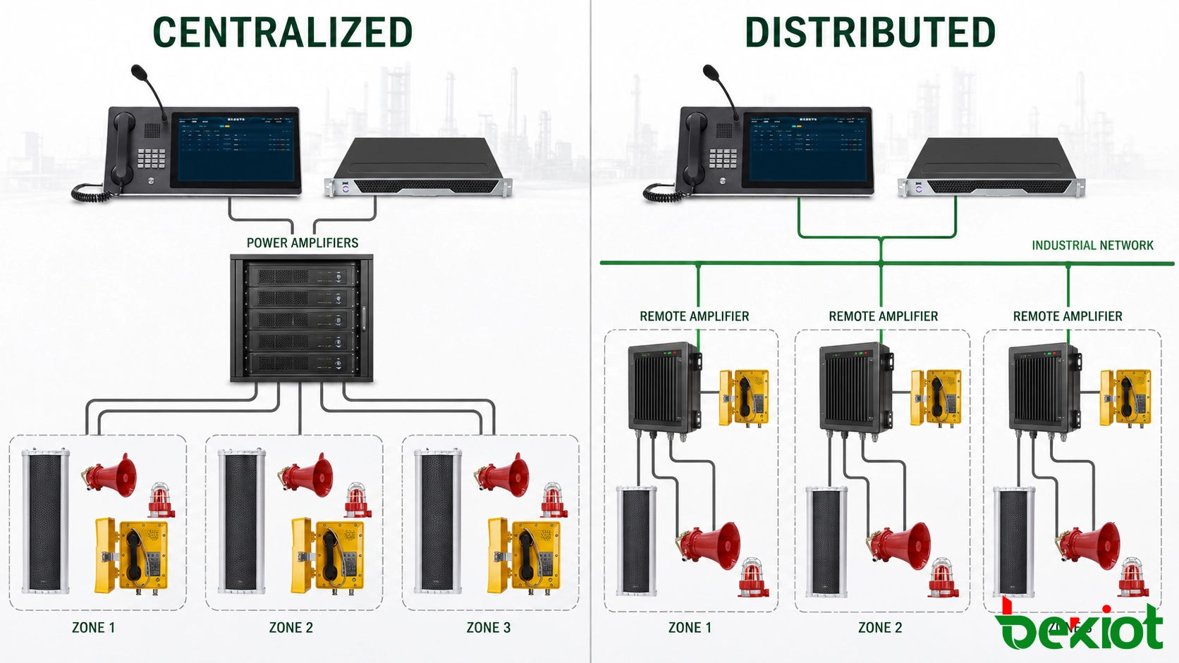
The correct choice normally depends on the physical layout of the site rather than the number of PAGA functions required.
A single production building may have relatively short cable routes and only a few paging zones. A refinery, mine, transport facility or large energy project may have communication areas separated by hundreds or even thousands of meters.
Using the same physical arrangement for both types of facility can lead to unnecessary cable runs, difficult expansion or excessive dependence on one equipment location.
2. How Does a Centralized PAGA Architecture Work?
In a centralized PAGA system, the main controller, audio processing equipment, interfaces and power amplifiers are normally installed together in a central equipment room.
Speaker circuits then run from the central amplifier racks to loudspeakers throughout the facility.
The basic structure is:
Central control equipment → central amplifier racks → field speaker circuits → loudspeakers
Centralized equipment simplifies maintenance
One of the main advantages is that most active equipment is concentrated in one protected location.
Technicians can inspect controllers, amplifiers, power supplies and interface modules without travelling between multiple remote cabinets. Equipment replacement and routine maintenance can also be easier because the main hardware is installed in the same room.
For relatively compact sites, this arrangement can be both practical and economical.
Centralized architecture is often suitable where:
The facility occupies a relatively compact area
Speaker cable distances remain manageable
The number of remote zones is limited
A secure communication room is available
Most areas can be reached through practical cable routes
Long cable routes are the main limitation
The disadvantages become more noticeable as the facility expands.
If a remote area requires several speaker circuits, every circuit may need to travel from that area back to the central amplifier room. This can increase the amount of cable installed in trenches, cable trays and distribution routes.
Expansion can also become less convenient. Adding a new paging zone at the edge of the facility may require another long cable route even when communication infrastructure already exists nearby.
Centralization also means that a relatively large amount of equipment can depend on the same room, rack location or supporting infrastructure.
This does not automatically make a centralized PAGA system unreliable. It does mean that the failure impact of central equipment, power supplies and shared cable routes needs to be evaluated carefully.
3. How Does a Distributed PAGA Architecture Work?
A distributed PAGA architecture separates overall system control from field-level amplification.
The main PAGA controller may remain in the central control room, while remote amplifier racks or audio nodes are installed closer to the areas they serve.
The basic structure becomes:
Central PAGA controller → site communication network → remote node → local amplifier → local speaker circuits
Instead of carrying every amplified speaker circuit over a long distance, audio and control information can travel through the site communication network before being amplified near the destination area.
Remote amplification can shorten speaker cable runs
Consider a tank farm or loading area located far from the main control building.
With centralized amplification, multiple speaker circuits may need to run all the way back to the main equipment room.
With a distributed design, an amplifier node can be installed closer to that area. The long-distance connection is handled through the communication network, while shorter local speaker circuits connect the remote amplifier to nearby loudspeakers.
This can reduce the concentration of long speaker cables and make the physical distribution of the system easier to manage.
Physical zones can follow the actual site layout
Distributed architecture is particularly useful when a facility contains clearly separated operating areas.
For example:
Main production area
Tank farm
Utility plant
Warehouse area
Administration building
Remote loading terminal
Instead of returning every speaker circuit to one location, selected areas can have their own amplification resources while remaining under the same PAGA control system.
This can also improve fault isolation. A fault affecting one remote amplifier node does not necessarily need to interrupt unrelated paging zones elsewhere on the site.
The communication network becomes part of the PAGA design
Distributed equipment still has to operate as one coordinated system.
Paging permissions, alarm priorities, zone selection, recorded messages and system status should remain consistent across all nodes.
For that reason, the network connecting central and remote PAGA equipment becomes part of the overall availability design.
Network topology, switch placement, communication paths and power availability should therefore be considered together with the PAGA equipment itself.
A distributed architecture can reduce long field cabling, but it should not simply transfer all system dependency from the speaker cables to a single unprotected network path.
4. When Does a Hybrid PAGA Architecture Make More Sense?
Many industrial facilities do not fit neatly into a purely centralized or purely distributed model.
A hybrid architecture allows the system to use centralized equipment where cable distances are short while installing remote amplifier nodes for distant areas.
For example, the main control room may contain the PAGA controller, operator consoles, system interfaces and amplifiers serving nearby buildings.
Remote process units, tunnels, substations or loading areas can then use network-connected amplifier nodes.
The architecture becomes:
Central PAGA control → central amplification for nearby zones + remote amplification for distant zones
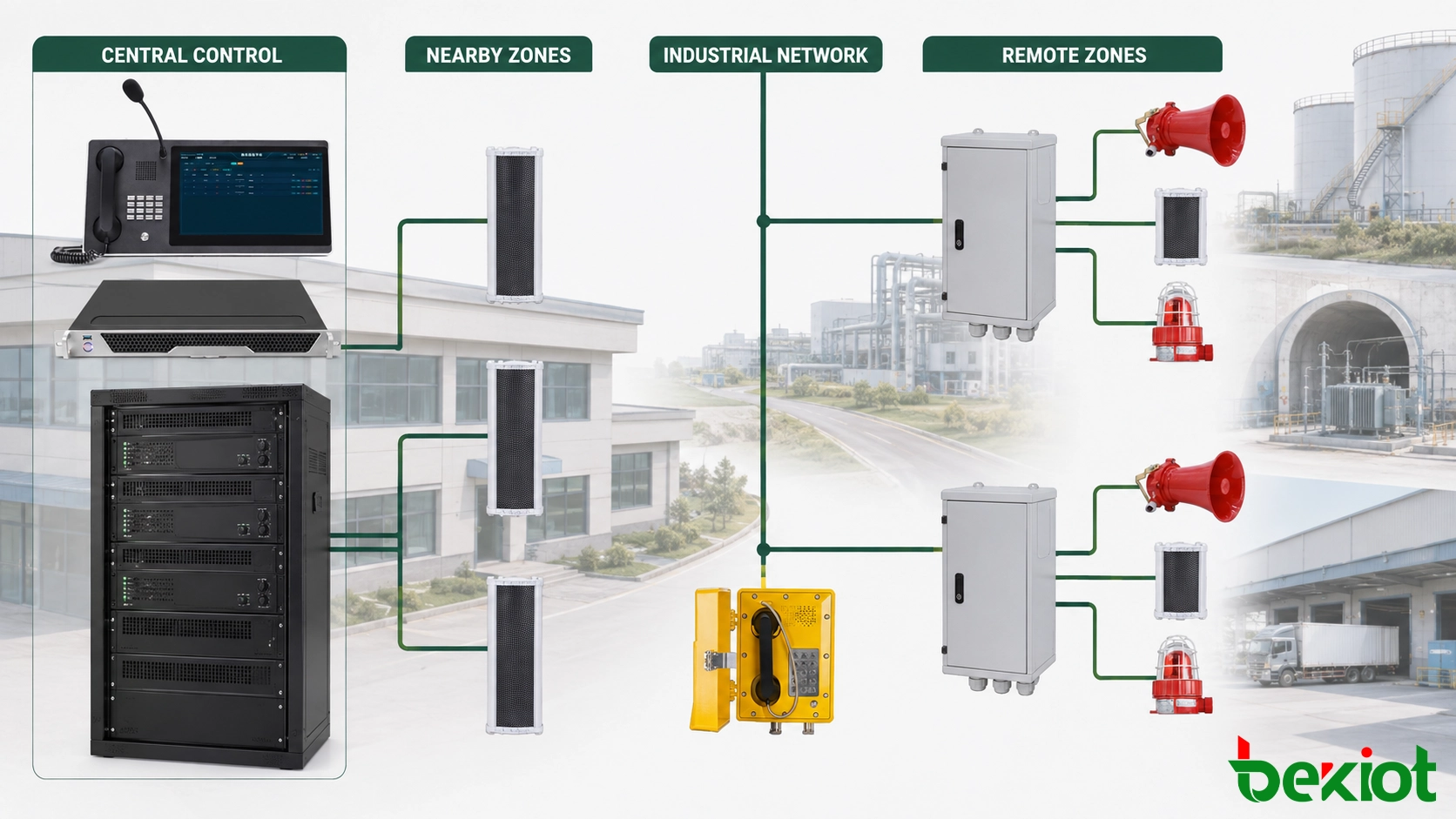
This arrangement allows equipment placement to follow the actual geography of the facility.
| Architecture | Typical Advantage | Main Design Consideration |
|---|---|---|
| Centralized | Concentrated equipment and simpler local maintenance | Long speaker circuits and central equipment dependency |
| Distributed | Shorter local speaker cabling and better geographic separation | Network availability, remote power and remote equipment access |
| Hybrid | Balances central control with local field distribution | Clear division between central and remote resources |
Compact industrial facilities
Where buildings and outdoor areas are close to the main equipment room, centralized amplification may remain the most straightforward approach.
Long tunnels and linear sites
For tunnels, railways and other long linear environments, distributing amplification at selected locations can avoid returning large numbers of speaker circuits to one central point.
Large process facilities
A refinery or large industrial plant may use central amplification for the main control building and nearby process areas while installing remote nodes for tank farms, utilities or other distant zones.
In these projects, physical distance often becomes a more useful design factor than simply counting the number of paging zones.
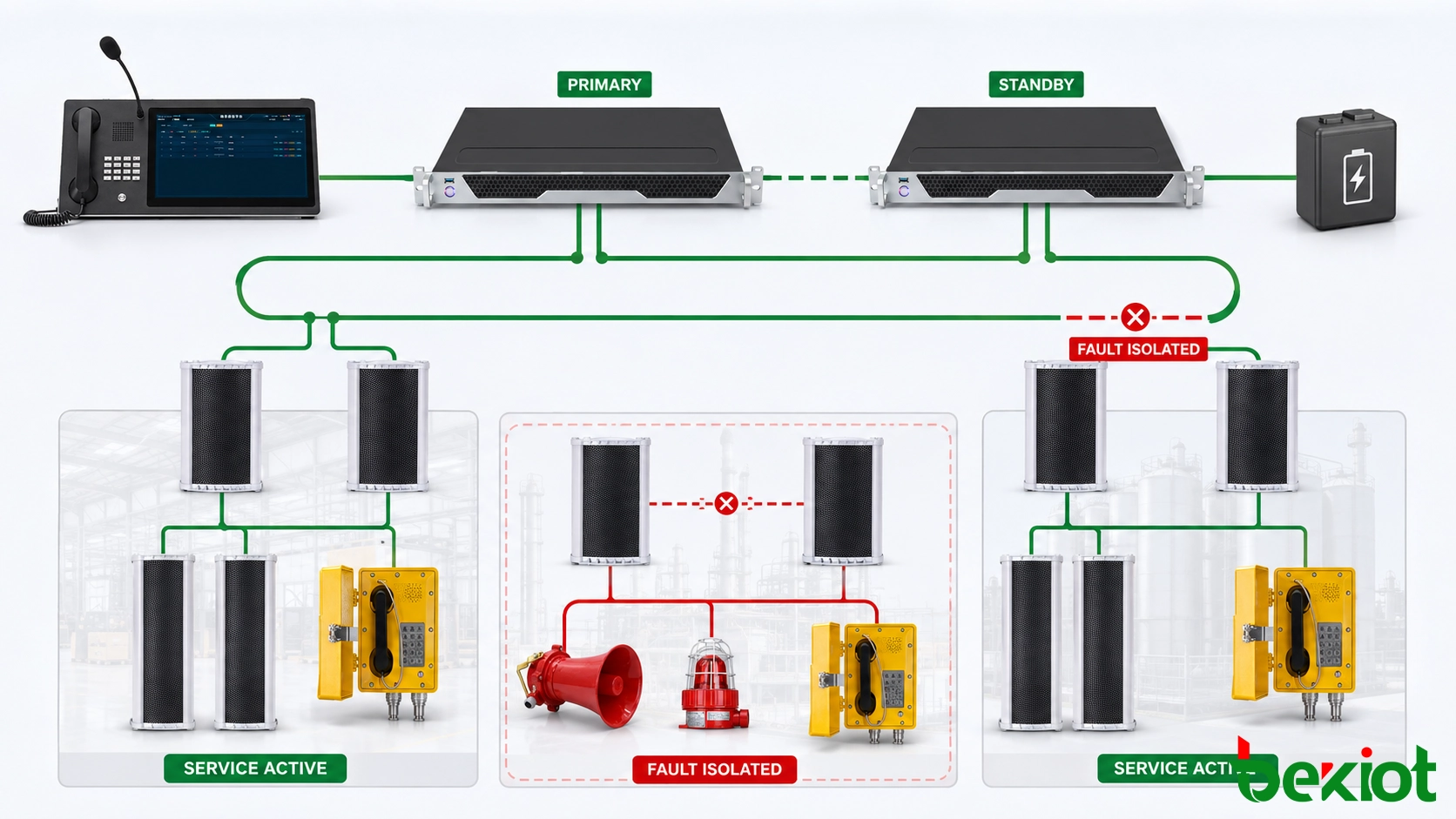
5. How Architecture Affects PAGA Redundancy and Fault Isolation
PAGA redundancy should not be considered separately from system architecture.
Before deciding where redundant equipment is required, the project should first identify what can fail and how much of the facility would be affected.
Controller failure
If a controller becomes unavailable, the design should define which paging and alarm functions must continue and whether another control path takes over.
Amplifier failure
An amplifier failure should be evaluated according to the communication zones it serves. Where required by the project, standby amplification or alternative audio paths can be provided to reduce service interruption.
Network failure
Network resilience becomes particularly important when remote PAGA nodes depend on IP or Ethernet communication.
If several remote areas share one communication path, a single network failure could affect multiple zones. Alternative paths or appropriate network redundancy may therefore be required depending on the project availability target.
Remote node failure
Distributed architecture can help reduce the physical impact of some failures because different areas use separate equipment.
However, this benefit depends on how the remote nodes are arranged. One remote node should not unnecessarily become a common dependency for several unrelated areas.
Power failure
Remote amplifier locations also need an appropriate power strategy.
Moving amplification closer to the field provides little benefit if the remote cabinet loses power during the event in which paging is most important. Backup power requirements should therefore be considered for both central and remote equipment.
Speaker circuit failure
Speaker-line supervision should also follow the physical architecture.
If an open circuit, short circuit or other field fault occurs, maintenance personnel should be able to identify which physical zone or speaker circuit is affected without searching through an unnecessarily large section of the system.
For this reason, a more useful redundancy question is not simply:
“Does the PAGA system have redundant equipment?”
A better engineering question is:
“If this controller, amplifier, network link, power source or speaker circuit fails, which paging zones remain available?”
This connects redundancy directly to the real operating impact of a failure.
For broader project planning covering capacity, interfaces, environmental requirements and system specification, see How to Select a PAGA System.
6. FAQ About PAGA Systems Architecture
Is centralized or distributed PAGA architecture better?
Neither architecture is universally better. Centralized systems are often practical for compact facilities with manageable cable distances. Distributed systems become more attractive when buildings, process areas or communication zones are widely separated. Large projects often use a combination of both.
When should remote PAGA amplifiers be considered?
Remote amplification is worth considering when large numbers of loudspeakers are located far from the main equipment room. Installing amplifiers closer to these zones can reduce long speaker cable runs and simplify local field distribution.
Can one PAGA system use both central and remote amplifiers?
Yes. This is a common hybrid approach. Nearby paging zones can use amplifiers in the main equipment room, while distant zones use network-connected remote amplifiers. Both remain under the same system control and alarm priority logic.
Does a distributed PAGA system need an IP network?
Many modern distributed PAGA systems use IP or Ethernet communication between central and remote equipment. The exact transport method depends on the platform, but the network should be treated as part of the system availability design rather than as an unrelated infrastructure layer.
Does distributed architecture automatically provide redundancy?
No. Distribution and redundancy address different design issues. Distributed equipment can reduce physical concentration and help isolate some failures, but controllers, networks, amplifiers, power supplies and field circuits still require an appropriate redundancy strategy.
The most suitable PAGA architecture is the one that follows the physical site instead of forcing every paging zone back to one equipment room.
For a compact facility, centralized amplification may provide the simplest installation. For a geographically dispersed site, remote nodes can reduce cable concentration and create clearer physical fault boundaries. Where both conditions exist in the same project, a hybrid architecture is often the more practical solution.
Before finalizing the architecture, the design should make three points clear: where the main communication resources are located, what happens when each critical part fails, and how easily new paging zones can be added in the future.