
Selecting a PAGA system starts long before a controller, amplifier, or loudspeaker model is chosen. The first job is to understand the site: where people work, how noisy each area is, which locations need independent paging, what should happen during an alarm, and which communication functions must remain available if part of the system fails.
These requirements determine the equipment, not the other way around. Two industrial sites of similar size can require very different PAGA configurations because their noise levels, hazardous areas, operating procedures, communication zones, and availability requirements are different.
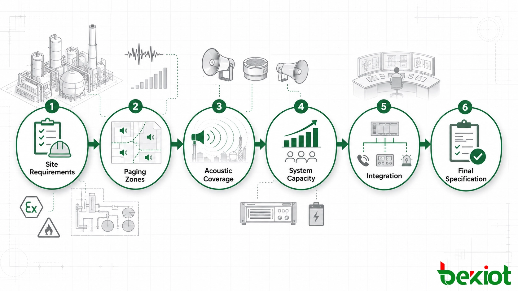
A practical selection process follows a clear sequence:
Site requirements → paging zones → acoustic coverage → system capacity → failure behaviour → integration → acceptance testing.
Using this sequence also makes supplier proposals easier to compare because each vendor is working from the same project inputs.
1. Define the Site Requirements Before Selecting Equipment
Start with a site requirement sheet rather than a product list. It should describe the physical environment and the communication tasks the system needs to support.
Key information normally includes:
Site layout and approximate dimensions
Buildings, process units, outdoor areas, tunnels, warehouses, and remote locations
Control rooms and operator positions
Normal and peak background noise
Indoor and outdoor installation conditions
Dust, humidity, corrosion, vibration, and temperature exposure
Hazardous-area classification where applicable
Routine paging requirements
Emergency communication scenarios
Existing telephone, radio, network, control, and alarm systems
Normal and backup power conditions
Future expansion plans
Each item can affect the final architecture. A high-noise process unit may require a different loudspeaker arrangement from an office building. A classified area may require appropriately certified field equipment. A geographically distributed site may need remote equipment nodes instead of placing every amplifier in one central room.
Emergency scenarios should also be defined at this stage. For example, a local equipment incident may require a message in one process area, while a wider emergency may require several adjacent zones or a site-wide broadcast.
| Project Input | Selection Impact |
|---|---|
| Background noise | Speaker output, quantity, position, and acoustic design |
| Hazardous area | Field equipment certification and installation requirements |
| Site layout | Zone structure, network topology, and equipment distribution |
| Emergency scenarios | Alarm logic, message priority, and target zones |
| Existing systems | Interfaces with F&G, DCS, SCADA, telephony, radio, and other platforms |
| Availability target | Redundancy, backup power, monitoring, and fault isolation |
The more complete this information is, the fewer assumptions suppliers need to make. That is important because quotations based on different assumptions may look comparable on price while representing very different technical solutions.
2. Convert the Site Layout into Paging Zones and Acoustic Coverage
Once the site conditions are clear, define how the facility needs to be addressed during normal operation and emergencies.
Build zones around operations
A PAGA zone should represent an area that may need to receive an independent message.
A plant may contain a production unit, loading area, tank farm, utility section, maintenance workshop, warehouse, control building, and administration area. These locations do not necessarily need the same broadcast at the same time.
Zone planning should answer practical questions:
Which areas need independent paging?
Which areas are normally grouped together?
Which operators can broadcast to each zone?
Which alarms override routine announcements?
Which zones are activated automatically by an external event?
When is a site-wide broadcast required?
Speaker circuits and communication zones are related, but they should not be treated as the same thing. Operational requirements should define the zone structure first; the electrical design can then support it.
Check the zone plan against real operating events
Take several expected alarm scenarios and follow the communication path from the initial event to the final broadcast.
If an alarm begins in one process area, identify which personnel need the first instruction, whether adjacent areas need a separate message, and what condition would expand the warning to a larger part of the site.
This often reveals that an area originally shown as one zone actually needs to be divided, or that two separate areas should be grouped during certain emergency conditions.
Use background noise to guide acoustic design
Speaker selection should be based on the acoustic environment, not only the size of the area.
Outdoor process areas, machinery spaces, loading zones, and other high-noise locations often require directional industrial horn speakers. Offices, corridors, control rooms, and enclosed service areas may use wall-mounted or ceiling speakers. Long narrow spaces may benefit from different coverage patterns than open production areas.
The required sound level should be evaluated against the actual background noise at the listener position. The aim is to provide enough level for alarms and voice messages to be recognized without simply increasing output as high as possible.
Excessive level can create its own problems, including reflections, poor speech clarity, uncomfortable listening conditions, and uneven coverage.
Include speech intelligibility where the project requires it
For emergency voice communication, audibility alone may not be enough. Personnel also need to understand the instruction.
Where speech intelligibility forms part of the project acceptance criteria, the required STI or STIPA performance should be defined according to the applicable project specification and standards.
Acoustic simulation can be useful for difficult spaces such as compressor areas, turbine halls, workshops, tunnels, terminals, or enclosed industrial buildings. It can help evaluate speaker direction, mounting position, coverage overlap, reflections, and expected intelligibility before installation.
The simulation requirement should identify the areas to be evaluated and the expected deliverables instead of simply asking the supplier to provide an “acoustic report.”
3. Calculate Amplifier, Controller, and Expansion Capacity
Once the speaker schedule is reasonably defined, system capacity can be calculated.
Calculate the connected speaker load
For each speaker circuit or amplifier channel, determine the total connected load from the number of loudspeakers and their selected power settings.
Amplifier selection should then consider:
Calculated connected speaker load
Required engineering margin
Future speaker expansion
Number of simultaneous broadcasts
Standby amplifier strategy
Speaker-line monitoring
Cable losses where relevant
A fixed reserve percentage should not be applied blindly to every project. The appropriate margin depends on the engineering specification, future expansion plan, amplifier architecture, and required availability.
Do not ignore cable distribution
Long field cable runs can influence system performance and installation cost. Large sites should therefore consider the relationship between amplifier location, speaker circuits, cable length, field cabinets, network infrastructure, and maintenance access.
In some installations, distributing amplification closer to the served areas can reduce long speaker cable runs and limit the impact of a local failure. In other projects, a more centralized architecture may remain practical.
The choice should follow the site layout rather than a fixed rule.
Check the limits beyond amplifier power
Enough amplifier wattage does not necessarily mean the complete platform has enough capacity.
The specification should also confirm the required number of:
Paging zones
Paging stations
Alarm inputs
Stored messages
Audio channels
Remote system nodes
Operator positions
Network endpoints
Third-party interfaces
Expansion should be considered while the system is being selected. Adding several new zones later should not require replacement of the main controller simply because the original design used every available port.
4. Define Failure Behaviour and External System Integration
Requirements such as “the PAGA system shall be redundant” or “the system shall integrate with DCS” are too broad for supplier selection.
Both need to be converted into specific operating behaviour.
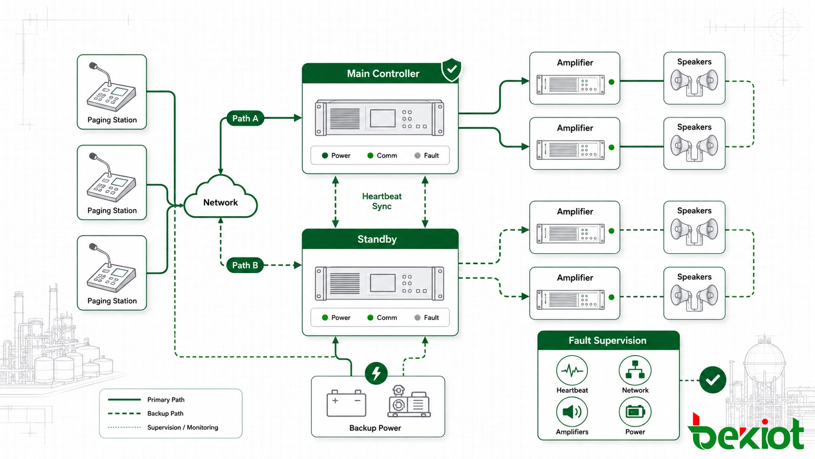
Specify what must happen after a failure
Review the architecture one failure at a time.
| Possible Failure | Question to Define |
|---|---|
| Controller failure | Which services must continue and whether automatic changeover is required |
| Amplifier failure | Whether standby capacity is required and which zones must remain available |
| Network failure | Whether another communication path is needed |
| Main power loss | Which functions must remain operational and for what period |
| Remote node failure | Whether the fault remains local or affects other areas |
| Speaker-line fault | How the fault is detected and reported |
This approach is more useful than automatically specifying the same redundancy structure for every industrial site.
A small facility and a large petrochemical, offshore, mining, or energy project can have very different consequences if part of the communication system becomes unavailable. The redundancy architecture should reflect those consequences.
Include fault supervision
Availability also depends on knowing that a fault has occurred.
Confirm whether the system can monitor:
Controller status
Amplifier status
Network connectivity
Remote node status
Paging station availability
Speaker-line open or short conditions
Power supply faults
External interface status
Fault information should be presented in a form that maintenance personnel can use to identify the affected device or area without searching through the complete system.
Define the full alarm workflow
For every automatic trigger or external interface, define the complete sequence:
Source → trigger → target zone → priority → audio → feedback → reset.
For example, a signal from a Fire & Gas system may need to start an alarm tone, play a recorded instruction in selected zones, interrupt lower-priority paging, display the event at an operator position, and remain active until the originating condition is cleared.
Possible integration points include:
Fire & Gas systems
DCS and PLC systems
SCADA
Industrial telephone systems
SIP or IP PBX platforms
Dispatch consoles
Radio communication systems
CCTV platforms
Emergency call stations
Third-party management software
Protocol support alone does not confirm that two systems will perform the required workflow. Event mapping, priority, signalling direction, acknowledgement, reset behaviour, and fault handling should all be confirmed before procurement.
Related solution: PAGA Systems
5. Compare Suppliers and Define Acceptance Tests
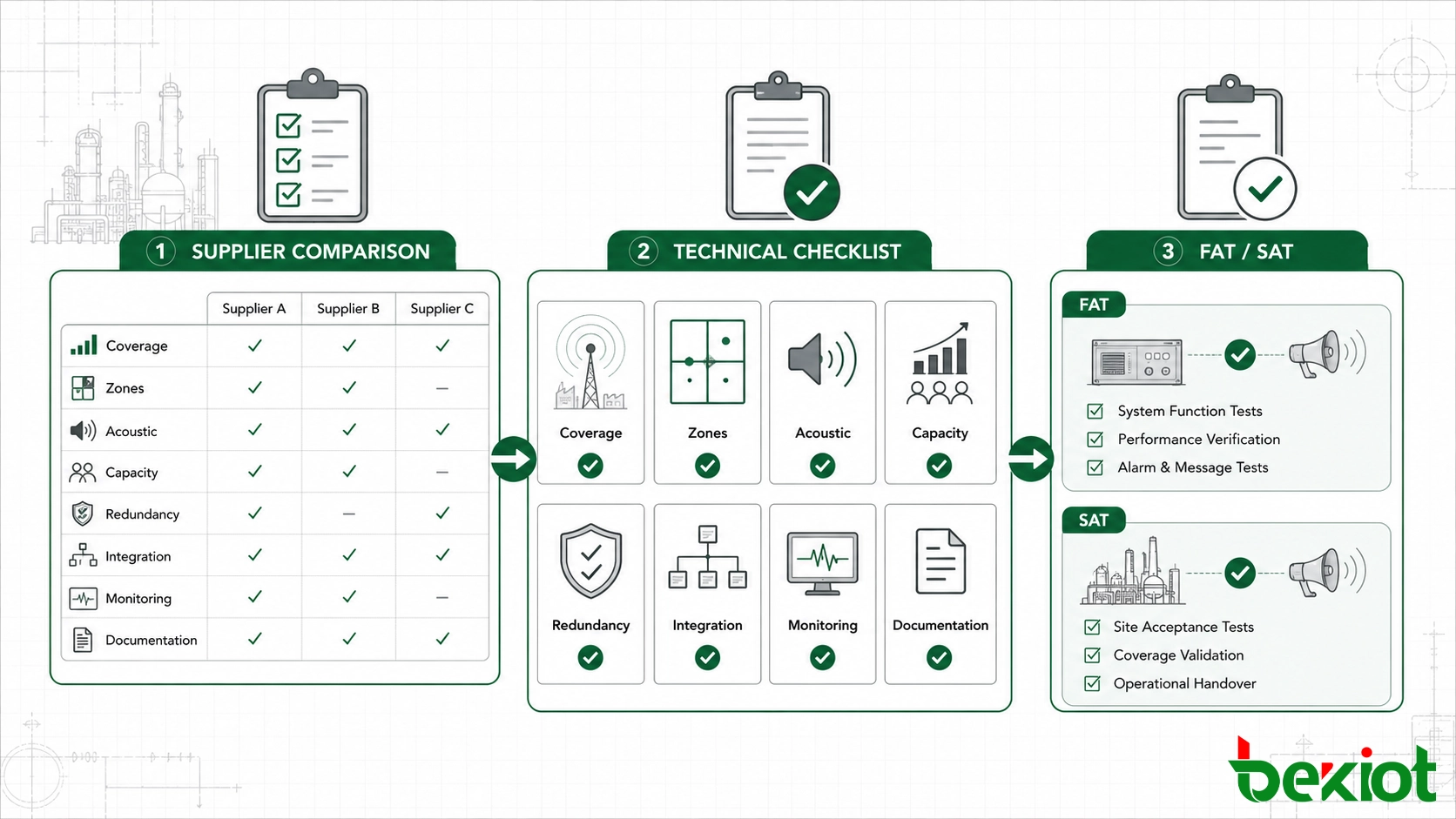
Once the site requirements, zones, acoustic design, capacity, failure behaviour, and interfaces are documented, supplier comparison becomes much more straightforward.
Every proposal should be checked against the same project requirements rather than the number of features shown in a product brochure.
| Selection Area | What to Verify |
|---|---|
| Coverage | All required indoor, outdoor, remote, and high-noise areas are included |
| Zoning | Individual zones, groups, and site-wide broadcasts match operating requirements |
| Acoustic design | Speaker type, location, output, and intelligibility requirements are addressed |
| Field equipment | Environmental and hazardous-area requirements match each installation location |
| System capacity | Speaker load, amplifier capacity, controller limits, and future expansion are documented |
| Availability | Required controller, amplifier, network, and power failures are addressed |
| Monitoring | Required equipment and speaker-line faults can be detected |
| Integration | External interfaces include complete operating logic |
| Maintenance | Fault diagnosis, configuration backup, event logging, and replacement are practical |
| Documentation | Drawings, zone schedules, interface lists, configuration records, and test procedures are included |
Do not compare purchase price alone
A lower initial equipment cost can be offset later by difficult expansion, long fault-recovery times, limited spare capacity, expensive interface development, or poor access to replacement parts.
For systems expected to operate for many years, supplier evaluation should also consider:
Configuration backup and recovery
Remote diagnostics
Module replacement
Future zone expansion
Software and firmware support
Spare-part availability
Operator and maintenance training
Final project documentation
Write FAT and SAT requirements before ordering
Acceptance criteria should be part of the specification, not added after installation.
Factory and site testing may include:
Individual zone paging
Grouped-zone paging
Site-wide emergency broadcast
Alarm priority and override
Automatic alarm activation
Recorded message playback
Controller or network failover where required
Standby amplifier operation where required
Main power failure and backup operation
Speaker-line fault indication
Third-party trigger and reset sequences
Event and fault logging
Sound pressure level measurements
STI or STIPA testing where specified
Actual site measurements are especially important in areas where noise, reverberation, or physical obstructions can affect speech coverage. A system that passes a configuration check in the equipment room may still need field adjustment before it meets the acoustic requirements at listener positions.
A good PAGA specification is not a long list of equipment parameters. It describes how communication must work at the site, which areas need to be reached, how much system capacity is required, what happens during a failure, how external alarms interact with the platform, and how final performance will be verified.
For projects that also use industrial telephones, dispatch consoles, radio, SIP communication, intercom, or emergency call systems, these connections should be considered during the PAGA selection stage rather than added after the main architecture has already been fixed.
Becke Telecom provides PAGA and industrial communication solutions for distributed industrial environments. System configurations can be planned around site zones, acoustic conditions, alarm workflows, availability requirements, existing communication infrastructure, and future expansion instead of relying on a fixed equipment package.
FAQ
What information should be prepared before requesting a PAGA quotation?
Prepare the site layout, operating areas, background noise information, hazardous-area requirements, required paging zones, emergency scenarios, operator locations, existing communication systems, integration requirements, availability targets, and expected future expansion. These inputs allow different suppliers to develop proposals from the same technical basis.
How should PAGA speaker capacity be selected?
Speaker selection should consider the background noise, listening distance, mounting position, coverage pattern, environmental conditions, and required speech performance in each area. The final speaker schedule then provides the basis for calculating amplifier capacity.
How is PAGA amplifier capacity calculated?
Calculate the connected speaker load for each circuit or amplifier channel, then include the engineering margin, expansion capacity, and standby requirements defined by the project. Cable distribution and simultaneous broadcast requirements should also be considered.
Does every PAGA system need the same redundancy architecture?
No. Redundancy should be based on the consequence of losing a controller, amplifier, network path, power source, or field node. The specification should define which services need to remain available after each failure rather than applying one fixed architecture to every project.
What should be included in PAGA site acceptance testing?
Typical tests include zone paging, emergency override, automatic alarm activation, recorded messages, external system interfaces, fault supervision, backup operation, event logging, and any required acoustic measurements such as SPL or STIPA. The exact test scope should match the project specification.