
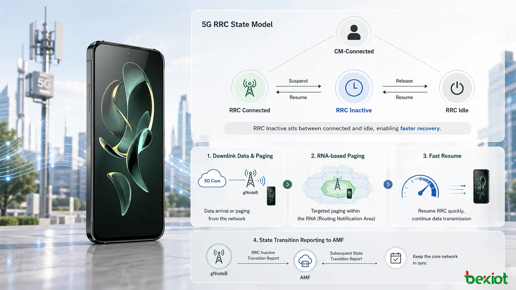
Between a fully connected UE and a fully idle UE, 5G introduces a state that looks quiet from the user side but remains technically meaningful inside NG-RAN. This state is RRC Inactive. It was added to 5G connection management to solve a practical problem: many devices need to return to data transmission quickly, but keeping every device in RRC Connected all the time would waste signaling resources, radio resources and battery power.
A smartphone may check background messages, a sensor may send short bursts of data, and an application may wake up briefly after a long silent period. These traffic patterns do not always justify a complete return to idle state followed by a full connection establishment procedure. RRC Inactive provides a middle layer. The UE can reduce activity, preserve key context and resume the connection faster when uplink or downlink data appears.
The important point is that RRC Inactive is not the same as RRC Idle. In RRC Idle, the UE is also in CM-IDLE from the core network perspective. In RRC Inactive, the UE remains in CM-CONNECTED, while the RRC layer is suspended from active connected operation. The gNodeB keeps UE context, the UE keeps AS context, and the network can move the UE back to RRC Connected through a resume procedure rather than starting everything from the beginning.
Why 5G Needs This State
5G connection management has to serve many traffic types at the same time. Some services need high throughput and continuous connection. Some only need short and occasional data exchange. Some terminals remain silent for long periods but must still respond quickly when the network or application needs them. If every UE were kept in RRC Connected, the network would carry unnecessary control overhead. If every inactive UE were pushed completely to RRC Idle, connection recovery could become slower and signaling-heavy.
RRC Inactive reduces this gap. The UE can stop active data processing in the RRC Connected sense, but important access-stratum context is not discarded. This allows a future resume procedure to recover the connection more quickly. From a user-experience point of view, the device can appear responsive. From a network point of view, the system avoids keeping active resources longer than needed.
This design is especially useful for applications that wake frequently but do not maintain long sessions. Messaging services, background synchronization, intermittent sensor reports, small uplink data bursts and short downlink notifications can all benefit from a state that supports faster return to connected operation.
In network architecture terms, RRC Inactive is also useful because it shifts part of the mobility and paging responsibility toward NG-RAN. The AMF does not need to treat every movement inside a local RAN notification area as a core-network mobility event. The gNodeB can manage the UE context and local paging behavior more efficiently.
How The State Is Defined
RRC Inactive has several defining characteristics. First, the UE is still considered CM-CONNECTED. This is a key difference from RRC Idle, where the UE is also in CM-IDLE. The 5G Core connection relationship remains in place, even though the RRC connection is not actively carrying normal connected-mode data.
Second, the state is mostly transparent to the core network. In normal operation, AMF does not need to manage the RRC Inactive state directly in the same way that NG-RAN does. The last serving gNodeB maintains UE context and knows the RAN Notification Area to which the UE belongs. This context retention makes fast recovery possible.
Third, the UE and gNodeB keep AS-layer context. Because the access-stratum context is preserved, the UE does not need a complete fresh setup when service resumes. Instead, the UE can use an RRC Resume process to return to RRC Connected.
The transition into RRC Inactive happens through an RRC Release message with suspend configuration. This is why the state is often discussed together with suspend and resume procedures. The network releases the active RRC connection but instructs the UE to suspend rather than fully discard its context.
When activity is needed again, the UE can move from RRC Inactive to RRC Connected. This may happen when the UE has uplink data to send or when it receives RAN paging for downlink data. If the inactivity condition persists too long, the gNodeB’s UE Inactivity Timer can eventually lead to N2 release, moving the UE toward RRC Idle and CM-IDLE.
What The UE Can Still Do
RRC Inactive does not mean the UE is frozen. Several procedures remain possible while the UE is not actively in RRC Connected. The UE can perform PLMN selection, receive system information broadcast, carry out cell reselection and respond to RAN-initiated paging. These functions help the UE remain reachable without maintaining a fully active RRC connection.
The network side also remains active in specific ways. NG-RAN manages the RAN Notification Area, configures DRX for RAN paging and retains the UE’s AS context. The gNodeB knows which RNA the UE belongs to, so it can decide the local paging range when data or signaling requires the UE to resume.
Another important point is that N2 and N3 connection context can remain established for the UE in this operating model. This matters when downlink data arrives. The UPF may still know the gNodeB address and can forward downlink data toward the last serving gNodeB. The gNodeB then triggers paging inside the configured RNA instead of forcing a core-network paging process from scratch.
These retained elements explain why RRC Inactive is useful but also more complex than simple idle behavior. The network must preserve enough context to recover quickly, but not so much active resource allocation that the state becomes equivalent to RRC Connected. The design balance is the value of this state.
How RNA Controls Mobility
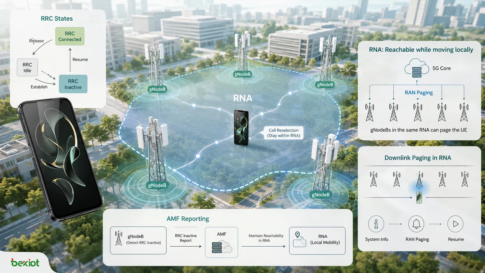
RNA means RAN Notification Area. It is a RAN-side notification area used for UEs in RRC Inactive. An RNA is made of several cells, usually under the same Tracking Area. When a UE moves inside its assigned RNA, it does not need to notify the network side every time it changes cell. This avoids unnecessary signaling when the UE is only moving locally.
RNA is identified by RNA ID. The identity is formed from TAC and RAN Area Code. The RAN Area Code range is 0 to 255. In practical terms, this gives NG-RAN a compact way to define local areas where inactive UEs can move without frequent updates.
The last serving gNodeB assigns the RNA ID through the suspend configuration in the RRC Release message. This is an important detail because the gNodeB that last served the UE becomes responsible for knowing the UE’s RNA context. If downlink data later appears, that gNodeB can decide how to page the UE within the proper area.
The UE must still update the network under certain conditions. If the periodic RNA update timer expires, or if the UE leaves the configured RNA, it should start the RNA update procedure. This keeps NG-RAN from losing practical knowledge of the UE’s local area while still avoiding excessive signaling for normal movement within the RNA.
RNA design affects paging efficiency. A very small RNA can cause frequent updates when the UE moves. A very large RNA can increase paging overhead because more cells may need to be paged when downlink data arrives. Good planning therefore depends on user mobility patterns, cell layout, gNodeB boundaries and expected service behavior.
How Downlink Data Is Delivered
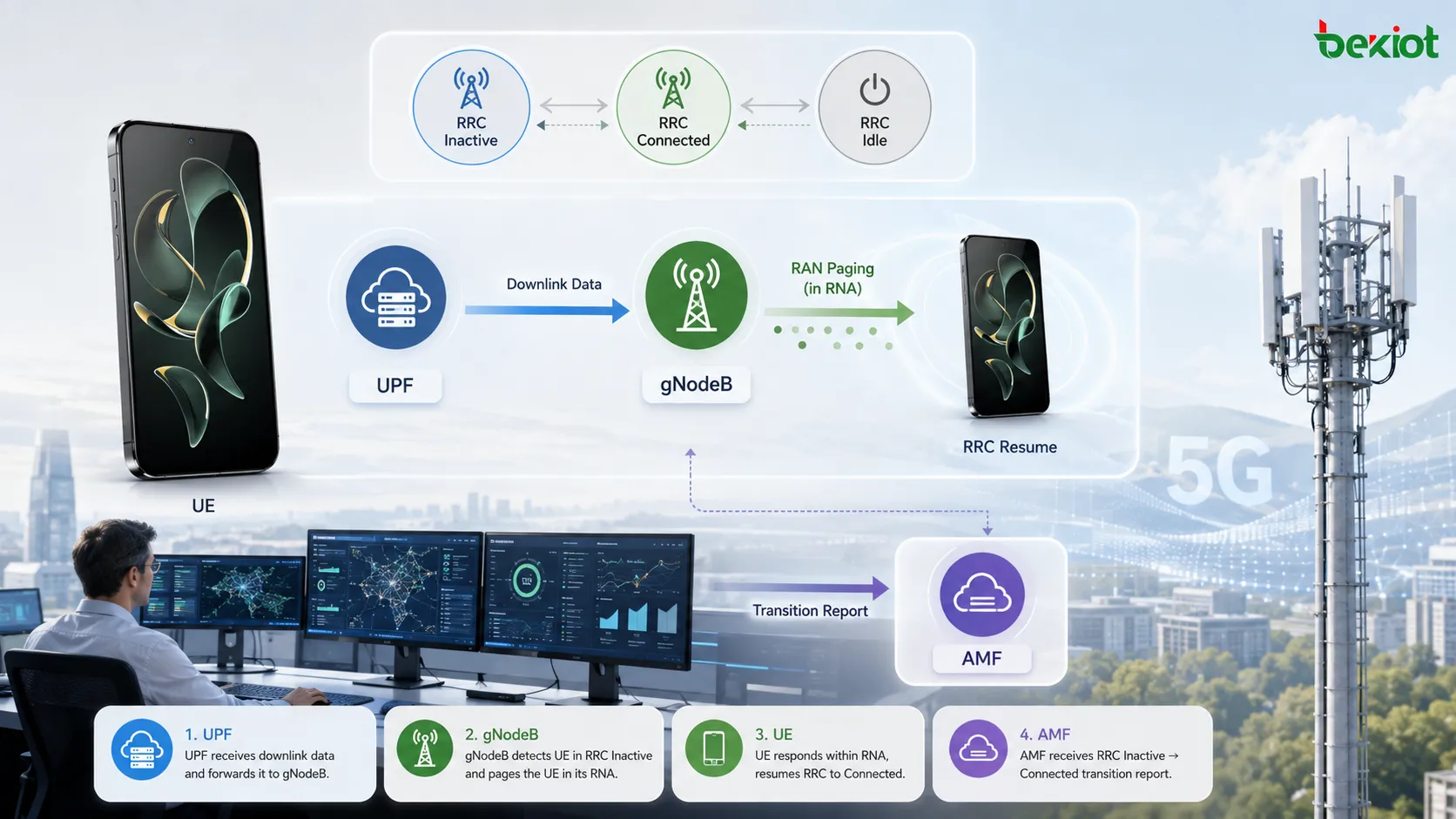
Downlink data handling is one of the clearest examples of why RRC Inactive exists. When downlink data arrives from the UPF while the UE is in RRC Inactive, the data can be sent toward the last serving gNodeB. The gNodeB then initiates paging inside the RNA because it knows the UE is inactive but locally reachable through RAN-level paging.
If all cells in the RNA belong to the last serving gNodeB, the process is relatively direct. The gNodeB pages the UE in the relevant cells. The UE receives the RAN paging message, starts the RRC Resume process and returns to RRC Connected. Once resumed, the UE can receive the downlink data.
If the RNA includes cells served by neighboring gNodeBs, the last serving gNodeB may use Xn signaling. It can send an XnAP RAN Paging message to the neighboring gNodeB so paging can occur in those cells as well. This allows the paging scope to follow the RNA rather than being limited only to the last serving gNodeB’s own cells.
The same general idea also applies when downlink UE-associated signaling arrives from AMF, except for cases such as UE Context Release Command where a different handling path applies. The key point is that NG-RAN can manage the paging procedure for an inactive UE without immediately treating it as a full idle-mode core-network paging case.
From a service perspective, the user experience depends on how quickly the UE receives the page and completes resume. From a network perspective, the system benefits because context is reused and signaling is more localized.
How Resume Transitions Work
RRC Inactive can return to RRC Connected from either the UE side or the network side. A UE-triggered transition happens when the UE has uplink data or a signaling need. The UE sends an RRC Resume Request toward the gNodeB. If the current gNodeB is not the last serving gNodeB, it may need to retrieve the UE context from the last serving gNodeB before completing the resume.
A typical UE-triggered process may include RRC Resume Request, Retrieve UE Context Request, Retrieve UE Context Response, RRC Resume and RRC Resume Complete. If the serving gNodeB changes, additional procedures may be needed, such as Xn-U Address Indication and Path Switch Request toward AMF. After path switching is handled, old context can be released where appropriate.
Network-triggered transition begins differently. The last serving gNodeB receives downlink data or relevant signaling and triggers RAN paging. The UE is paged inside the RNA. After receiving paging, the UE resumes from RRC Inactive and returns to RRC Connected so the pending data or signaling can be handled.
These transitions are designed to be lighter than a full connection setup from idle. That does not mean they are trivial. Correct behavior depends on stored context, gNodeB coordination, AMF path switching when needed and clean context release after the new serving path is established.
The timer path is also important. If the UE remains inactive beyond the gNodeB’s UE Inactivity Timer policy, the network can move the UE toward RRC Idle. This usually involves N2 release and changes the core network state to CM-IDLE. At that point, the fast resume advantages of RRC Inactive no longer apply.
How AMF Receives State Reports
RRC Inactive is often described as transparent to the core network, but that statement needs careful interpretation. In general, AMF does not directly control the UE’s RRC state in the same way NG-RAN does. However, AMF can request reporting of RRC state transitions through NGAP signaling behavior.
AMF can include an RRC Inactive Transition Report Request parameter in messages such as Initial Context Setup Request or UE Context Modification Request. When the request is set to subsequent state transition report, the gNodeB should report when the UE enters or leaves RRC Inactive.
When a state change occurs, the gNodeB sends an RRC Inactive Transition Report to AMF. The report includes the RRC State value, such as Inactive or Connected. This mechanism gives AMF visibility when it has requested it, without changing the basic fact that NG-RAN manages the RRC Inactive behavior.
This reporting capability is useful for network coordination, policy awareness and operational monitoring. It also helps explain why RRC Inactive should not be described too simply as completely invisible to the core network. A better view is that it is mainly RAN-managed, while AMF can obtain state transition information under specified conditions.
For engineering analysis, this distinction matters. If a procedure fails, troubleshooting may need to look at both RAN behavior and NGAP reporting behavior. The UE state, gNodeB context, RNA configuration, RAN paging, AMF reporting request and path switch handling can all influence the final result.
FAQ
Why is RRC Inactive not the same as RRC Idle?
RRC Inactive keeps the UE in CM-Connected and preserves access-stratum context, while RRC Idle belongs to an idle core-network relationship where connection recovery requires a heavier procedure.
What triggers the UE to resume from RRC Inactive?
Resume may be triggered by uplink data from the UE, a signaling need from the UE, or RAN paging caused by downlink data or supported downlink signaling.
Why does RNA reduce signaling?
RNA allows the UE to move within a defined RAN notification area without informing the network about every cell change, reducing unnecessary local mobility signaling.
What happens if the UE leaves its RNA?
The UE should start an RNA update procedure so NG-RAN can refresh the area information used for local paging and inactive-state reachability.
Why might neighboring gNodeBs be involved in paging?
If the RNA includes cells served by neighboring gNodeBs, the last serving gNodeB may send XnAP RAN Paging so those neighboring cells can also page the UE.
When does AMF learn about RRC state changes?
AMF can receive state transition reports when it has requested them through the RRC Inactive Transition Report Request parameter in supported NGAP procedures.
RRC Inactive is one of the most practical connection-management improvements in 5G. It keeps enough context to resume quickly, reduces unnecessary active connection resource usage, supports local movement through RNA and allows NG-RAN to handle paging more efficiently. Its value comes from balance: faster than returning from full idle, lighter than staying fully connected, and flexible enough to support modern mobile traffic patterns.