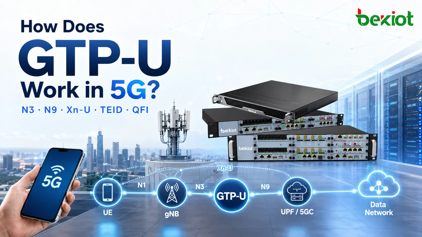
When a UE opens a video app, the actual user traffic has to travel from the gNB to the UPF before reaching the data network. The control plane establishes the PDU Session, assigns addresses, and installs forwarding rules, but the protocol that actually carries user IP packets across the 5G access and core user plane is GTP-U. Understanding GTP-U requires more than remembering "UDP port 2152" and "TEID." In 5G, a single N3 tunnel may carry multiple QoS Flows, while path supervision, unknown tunnel handling, and user-plane cleanup after mobility events also rely on GTP-U management messages. Looking at the protocol stack, tunnels, TEIDs, QFIs, and management procedures as one complete user-plane path makes it much easier to understand how 5G traffic actually reaches the UPF.
Where Does GTP-U Sit in the 5G Architecture?
GTP-U stands for GPRS Tunnelling Protocol for the User Plane. In the 5G user-plane architecture, it is primarily used to encapsulate and transport upper-layer user traffic between user-plane nodes.
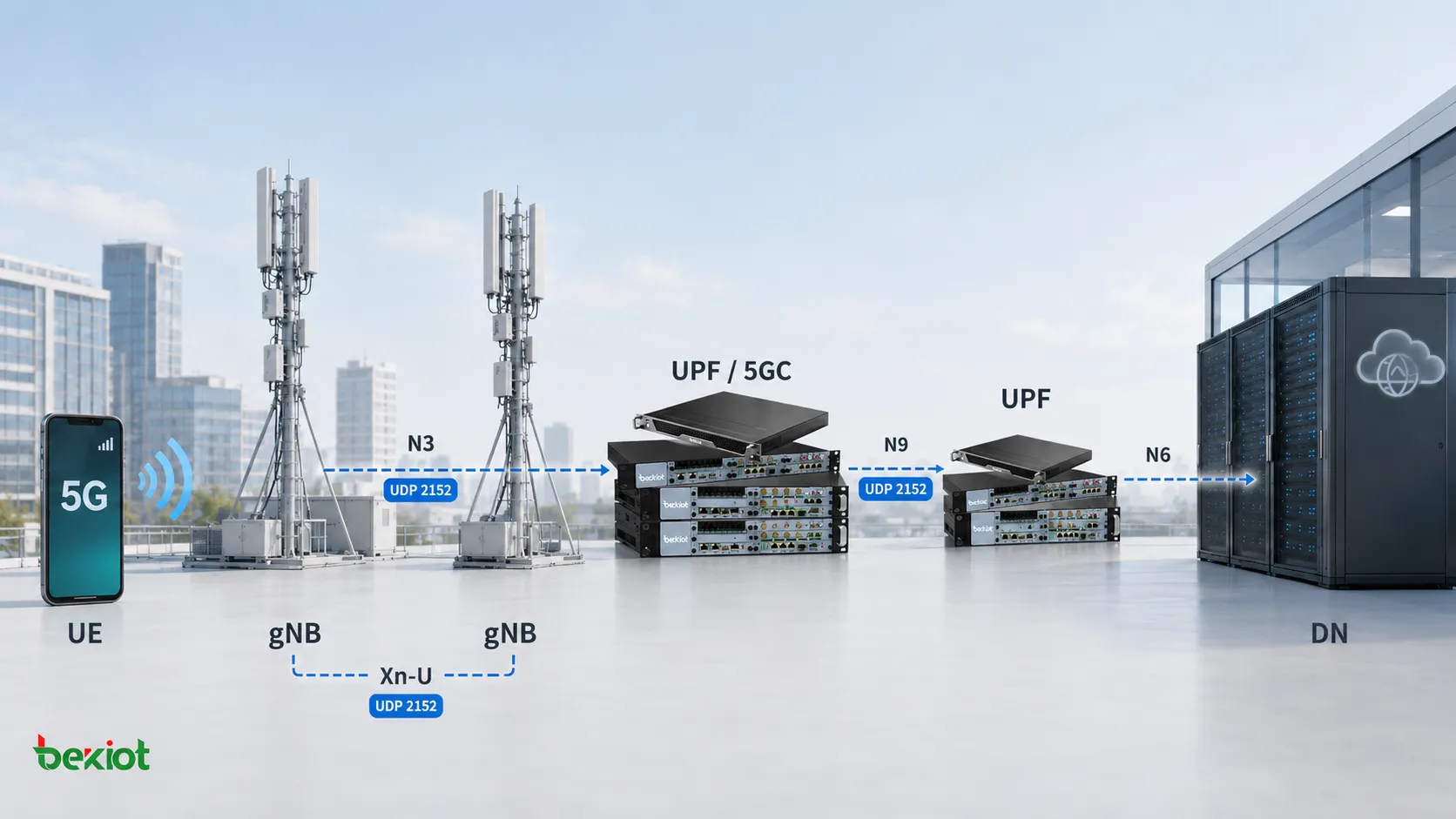
From the 5G Core perspective, the two most common interfaces using GTP-U are N3 and N9. N3 connects the gNB to the UPF and carries user traffic between the radio access network and the 5G Core. N9 is used between UPFs. Within the RAN, Xn-U between gNBs can also use GTP-U.
This is quite different from the 5G control-plane architecture. Network functions such as the AMF and SMF use service-based interfaces that largely rely on HTTP/2, while the user-plane path continues to use GTP-U for carrying the subscriber's actual traffic. The move to a Service-Based Architecture in 5G did not mean that the user plane itself moved to HTTP.
GTP-U runs over UDP and continues to use UDP port 2152. If the protocol stack is viewed from a user's application packet downward, the structure can be understood as follows.
Application traffic first becomes a TCP or UDP packet and then an IP packet belonging to the UE. Once it enters the 5G user plane, that original user packet is encapsulated inside GTP-U. An outer UDP header, outer IP header, and lower-layer Ethernet framing are then added for transport between the GTP-U endpoints.
This means a packet capture may contain two different sets of IP addresses. The inner IP addresses describe communication between the UE and the application server on the data network, while the outer IP addresses are used between GTP-U tunnel endpoints such as the gNB and UPF. Mixing up the inner and outer IP headers is a common source of confusion when troubleshooting N3 traffic.
What Is the Difference Between a GTP Path, Tunnel, and TEID?
GTP Path, GTP Tunnel, Tunnel Endpoint, and TEID are closely related terms, but they describe different layers of the GTP-U transport model.
A GTP Path can be viewed as the connectionless communication path between two GTP tunnel endpoints. If a gNB and a UPF can exchange GTP-U packets across the IP network, a GTP Path exists between those endpoints. Multiple GTP-U tunnels can share the same Path.
A GTP Tunnel represents a more specific logical user-plane tunnel. A GTP-U tunnel is identified using a combination of the TEID, IP addressing, and UDP transport information, while the tunnel endpoint itself is identified by the node IP address and UDP port.
The TEID, or Tunnel Endpoint Identifier, is one of the most important fields in GTP-U. In the GTPv1-U basic header, the TEID is four bytes long. When a GTP-U packet reaches the receiving node, the receiver uses the TEID together with its local tunnel context to determine which user-plane tunnel the packet belongs to and which PDU Session or forwarding context should process it.
This is also why a TEID should never be interpreted in isolation. The same numerical TEID value can appear in different tunnel contexts. If the packets belong to different GTP endpoints or different directions, they are not necessarily part of the same tunnel.
Two additional terms are useful when looking at the payload itself. A T-PDU is the original upper-layer user data, while a G-PDU is the T-PDU after the GTP-U header has been added. What is carried across N3 is therefore not the UE's raw IP packet alone, but a GTP-U-encapsulated G-PDU.
GTP-U is also not limited to carrying user data. It has its own management messages. As a result, seeing UDP port 2152 in a packet capture does not automatically mean the packet belongs to user application traffic. Echo Request, Echo Response, Error Indication, End Marker, and other GTP-U messages use the same protocol framework.
Why Does 5G Need QFI If It Already Has TEID?
If GTP-U is first learned from a 4G perspective, it is easy to assume that identifying the TEID is enough to identify the bearer. In 5G, that assumption is no longer complete.
The 4G QoS architecture is based on EPS Bearers. Different bearers have their own user-plane transport contexts and GTP-U tunnels, so the tunnel and TEID naturally help distinguish different bearer traffic.
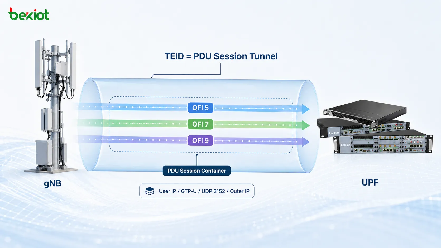
5G changes the QoS model to PDU Session plus QoS Flow. A single PDU Session may contain one or more QoS Flows, and a DRB may also carry one or more QoS Flows. However, N3 does not create a separate GTP-U tunnel for every QoS Flow within the same PDU Session.
In other words, the TEID can identify the GTP-U tunnel associated with the PDU Session, but several QoS Flows may still share that same tunnel.
That raises another question: how does the receiving node know which QoS Flow an individual packet belongs to?
This is one of the main reasons for the PDU Session Container extension header. 5G uses this GTP-U extension header to carry PDU Session-related user-plane information, including the QFI, or QoS Flow Identifier.
The QFI is a 6-bit identifier used to identify a QoS Flow. When analyzing 5G N3 traffic, TEID and QFI can therefore be understood at two different levels:
The TEID identifies the GTP-U tunnel or PDU Session context, while the QFI identifies the specific QoS Flow carried inside that tunnel.
The downlink PDU Session Container can also carry information such as RQI and PPI. RQI is used for Reflective QoS-related signaling, while PPI is associated with Paging Policy Differentiation and can support different paging treatment for different types of traffic within the same PDU Session.
The E bit in the GTP-U basic header indicates whether an Extension Header follows. This means that not every GTP-U packet necessarily carries the same extension headers. Whether a PDU Session Container is present depends on the packet and the function being performed.
What Actually Happens to an N3 User Packet?
The previous concepts become much easier to understand when they are placed into a real uplink packet flow.
Assume a UE is accessing an online video service. The UE first generates application traffic, which is carried over TCP or UDP and then placed inside a normal IP packet. In this inner IP header, the source address is the UE's assigned IP address, while the destination address belongs to the internet application server.
When the packet reaches the gNB, the gNB does not simply forward the UE's IP packet directly to the UPF. Instead, it applies GTP-U encapsulation based on the current user-plane context of the PDU Session.
The GTP-U header contains the relevant TEID. If the packet needs to identify a specific QoS Flow, the PDU Session Container can also carry the QFI. The gNB then adds the UDP header, with destination port 2152, followed by the outer IP header.
At this point, the outer IP addresses no longer describe the UE-to-internet communication. They represent the transport relationship between the gNB N3 interface and the UPF N3 interface.
When the packet reaches the UPF, the process is reversed. The UPF receives the packet based on the outer transport information, reads the TEID to locate the correct user-plane tunnel context, processes the QFI and other extension information where required, removes the GTP-U encapsulation, and then forwards the original UE IP packet toward the data network.
When troubleshooting N3 traffic with Wireshark or another packet-analysis tool, a useful approach is to work from the outside inward. First verify the outer gNB and UPF IP addresses, then UDP port 2152, followed by the TEID, the PDU Session Container and QFI where present, and only then inspect the user's inner IP, TCP or UDP, and application-layer traffic.
This method is often more effective than starting with the application packet because many N3 faults are caused by tunnel context, TEID, or endpoint issues rather than by the user's application itself.
Why Does GTP-U Need Its Own Management Messages?
Although GTP-U is a user-plane protocol, it is not limited to G-PDU user-data messages. It also defines path-management and tunnel-management messages that help keep the user-plane transport operational.
Echo Request and Echo Response Check Path Availability
An Echo Request is used to check whether the GTP Path and the peer GTP node are reachable and operational. The peer responds with an Echo Response.
These messages test the basic relationship between two GTP endpoints. If a gNB repeatedly fails to receive Echo Responses from a UPF, the issue may no longer be limited to one UE or one PDU Session. It can indicate a problem with the GTP Path itself or with the peer node.
GTP-U also defines the Supported Extension Headers Notification message, which allows a node to indicate which GTP extension headers it supports. This becomes relevant when 5G user-plane features depend on extension headers such as the PDU Session Container.
Error Indication Handles Unknown TEIDs
If a GTP endpoint receives a G-PDU but cannot find a local EPS Bearer or PDU Session context corresponding to the received TEID, and the TEID is not zero, it can send an Error Indication to the peer.
This tells the sending node that it is forwarding data toward a user-plane tunnel that the receiving side no longer recognizes.
If Error Indication messages appear repeatedly during troubleshooting, the first things to check are whether both endpoints have consistent TEID state and whether a PDU Session update, mobility procedure, or user-plane path change left the two sides out of sync.
End Marker Helps Finish a User-Plane Path Switch
The End Marker is commonly associated with mobility and user-plane path switching. It indicates that the last G-PDU on the old GTP-U path has been sent and that subsequent user traffic should no longer continue along that previous path.
For example, when a UE moves from a source gNB to a target gNB, the core-network user-plane path may also change. Traffic should not continue indefinitely over the old path, otherwise the old and new paths could overlap and create packet-ordering or forwarding problems.
The End Marker is therefore not simply a "delete tunnel" notification. It acts more like a boundary marker for the old user-plane path, informing the receiving side that the last packet on that path has already been delivered.
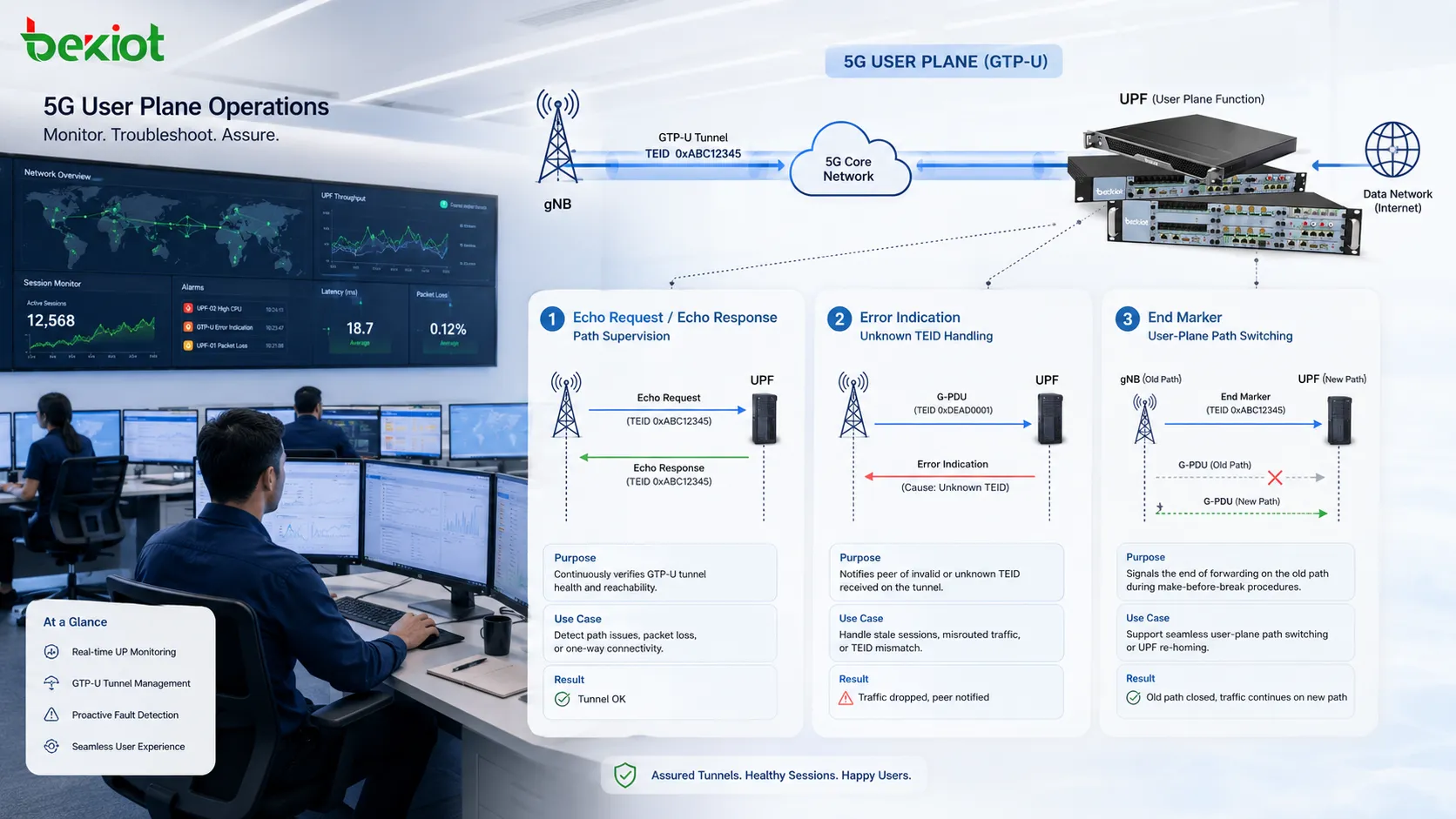
Once these mechanisms are viewed together, the role of GTP-U becomes much clearer. It is not simply a protocol that adds a TEID in front of a user's IP packet. It provides a complete user-plane tunneling framework that can be identified, monitored, managed, and updated as network state changes.
A practical troubleshooting sequence for 5G GTP-U is therefore to first confirm that the GTP endpoints and Path are healthy, then verify the TEID and Tunnel context, inspect the PDU Session Container and QFI where applicable, and finally move inward to the original user traffic. If the issue occurs during mobility or path updates, Error Indication and End Marker messages should also be reviewed.
Following this order turns an N3 packet capture from a large collection of UDP 2152 packets into a user-plane forwarding path that can be reconstructed layer by layer.
FAQ
Does Every Packet on UDP Port 2152 Carry User Traffic?
No. G-PDU messages carry user-plane data over GTP-U and UDP port 2152, but GTP-U management messages such as Echo Request, Echo Response, Error Indication, End Marker, and Supported Extension Headers Notification also use the same protocol framework. The GTP-U Message Type should be checked to determine what the packet actually represents.
Must a TEID Be Globally Unique Across the Entire 5G Network?
No. A TEID should not be treated as a globally unique network-wide identifier. GTP-U tunnel identification also depends on the tunnel endpoints, IP addressing, transport information, and direction. Troubleshooting should therefore consider the complete tunnel context rather than comparing TEID values alone.
Does Every 5G GTP-U Packet Include a PDU Session Container?
No. The PDU Session Container is a GTP-U extension header, and whether it is present depends on the packet and the function being performed. The E bit in the GTP-U basic header indicates whether additional Extension Headers follow, so not every N3 packet has the same header structure.
Does an End Marker Mean the Entire PDU Session Has Been Released?
Not necessarily. An End Marker primarily indicates that traffic on a particular GTP-U user-plane path has reached its end and is commonly seen during path switching after mobility events. It marks the end of traffic on that path rather than representing the complete PDU Session release procedure.