A 5G device can be registered to the network without immediately building a user data path. That small design change says a lot about how 5GC session management differs from older mobile core systems. In 4G, the attach process was closely tied to creating a default PDN connection and a default bearer. In 5G, registration and session establishment are separated more clearly, which gives the network more freedom to decide when a user plane path is really needed.
5GC session management is the control layer that decides how a UE connects to a data network, which PDU session is created, which DNN is used, which slice information applies, what QoS rules are assigned, which UPF anchors traffic, and how continuity should be handled when the UE moves. It is not only a renamed version of 4G bearer management. It is a more flexible framework built for mobile broadband, voice over 5G, enterprise access, low-latency services, local area data networks and edge computing.
This is why session management becomes one of the central concepts in the 5G Core. Mobility management tells the network where the UE is and whether it is reachable. Session management tells the network what kind of service path the UE needs, which data network should be reached, how traffic should be classified, and how user-plane resources should be controlled. The two functions cooperate closely, but they are no longer handled as one combined control block.
Why Session Control Changed
The biggest architectural change is the separation of mobility management and session management. In 5G Core, AMF is responsible for NAS mobility management, while SMF is responsible for session management. NAS-SM messages do not get fully processed inside AMF. Instead, AMF forwards session management signaling toward SMF through the N11 interface. This means AMF does not maintain the UE’s session management context in the same way older combined control logic did.
This separation makes the 5G Core cleaner. AMF can focus on registration, access control, reachability, mobility state and location-related procedures. SMF can focus on PDU session establishment, modification, release, DNN handling, UPF selection, QoS rule control, session continuity and charging-related parameters. When these responsibilities are separated, the network can scale each function according to its own workload.
The change also fits the service direction of 5G. A smartphone, an industrial sensor, a vehicle, a private network device and an edge computing application may all use 5G differently. Some devices need frequent data sessions. Some may register and remain silent. Some may need only local access inside a defined area. Some may require stable IP continuity across movement. A single “always create a default bearer at power-on” model is not flexible enough for that variety.
In 5G, a UE can perform registration without immediately establishing a PDU session. This avoids creating user-plane resources before any service actually needs them. For massive IoT and machine-type access, that is especially important. The network can keep the UE known and reachable while avoiding unnecessary data-path setup.
The separation of mobility and session control also affects subscriber data. UDM subscription data is divided into mobility-related and session-related parts. AMF receives mobility subscription data, SMF uses session management subscription data, and AMF can receive SMF selection data to help choose the correct SMF during PDU session establishment. This structure makes the core network more modular and easier to align with slicing, DNN-specific policy and differentiated service models.
From PDN To PDU
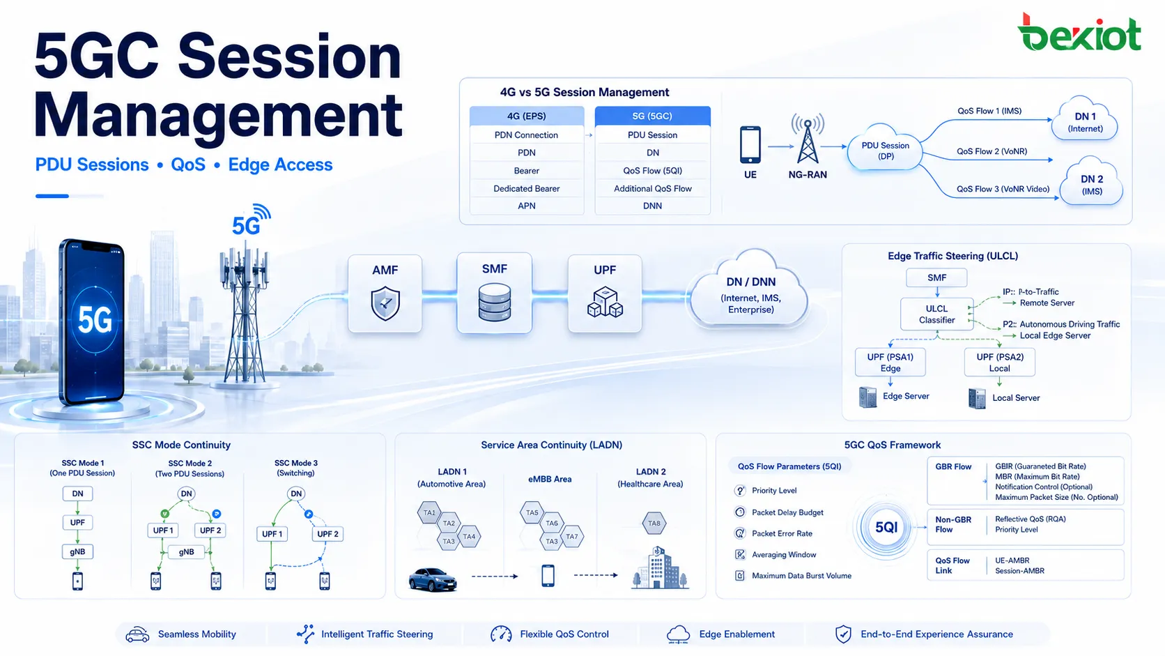
Many 5G session management terms have roots in 4G, but the terminology and structure have changed. The 4G PDN connection becomes a PDU session in 5G. The 4G PDN becomes DN, or Data Network. The 4G APN becomes DNN, or Data Network Name. The 4G default bearer is replaced by the default QoS Flow, while dedicated bearers become additional or non-default QoS Flows.
This change is not only cosmetic. A PDU session is designed to support different types of packet data unit connectivity. In 4G, PDN Type mainly covered IPv4, IPv6 and IPv4v6. In 5G, PDU session type adds more flexibility by supporting Ethernet and Unstructured data as non-IP options. This is important because 5G is expected to support more than traditional internet access. Industrial devices, enterprise private networks and special service environments may require service models that are not limited to ordinary IP connectivity.
| 4G Term | 5G Term | Practical Meaning |
|---|---|---|
| PDN Connection | PDU Session | The user data session between UE and a data network through the 5G Core. |
| PDN | DN | The target data network, such as Internet, IMS or a local service network. |
| APN | DNN | The data network name used to select service access and session policy. |
| Default Bearer | Default QoS Flow | The initial QoS Flow created inside a PDU session. |
| Dedicated Bearer | Additional QoS Flow | A service-specific QoS Flow added for differentiated treatment. |
A UE may establish one PDU session for general internet access and another for IMS. Inside the IMS-related PDU session, different QoS Flows can be used for SIP signaling, VoNR audio and VoNR video. The important difference is that 5G no longer maps every service to a separate EPS bearer in the same manner. Instead, QoS Flow becomes the key granularity for service treatment, while DRB mapping is controlled on the radio side by gNB.
This model allows finer service control. A single PDU session can carry multiple QoS Flows, and each QoS Flow can receive a different 5QI, ARP and QoS treatment. For enterprise and operator services, this makes it easier to support multiple traffic classes without forcing every service into a rigid bearer model.
How SMF Takes Control
SMF is the main control function for 5GC session management. It handles PDU session establishment, modification and release. It selects or controls UPF usage, manages session-related policy interaction, assigns QoS rules, and determines how the user plane should be built. When AMF receives NAS-SM signaling from the UE, it forwards that information to SMF rather than processing the full session logic locally.
This design makes AMF and SMF work like two coordinated layers. AMF knows the UE’s access and mobility state. SMF knows the service session requirements. When a PDU session is requested, AMF helps carry signaling and provides access-related context, while SMF decides how the session should be created according to DNN, S-NSSAI, subscription data, policy control and user-plane availability.
SMF also plays a central role in selecting SSC Mode. The selection is not random. It depends on the SSC Mode requested by the UE, the subscribed SSC Mode in UDM data, and the allowed SSC Mode set. Once the PDU session is established, its SSC Mode cannot be changed. That makes the selection decision important at the beginning of the session.
Another key responsibility is user-plane resource control. SMF can activate or deactivate user-plane resources, release a PDU session, or adjust related session handling depending on mobility, service area, policy and access state. For LADN, for example, when SMF learns that a UE has left the LADN service area, it may release the related PDU session or deactivate user-plane resources.
SMF also controls traffic steering for edge computing scenarios. When UPFs are used as anchors and classifiers, SMF can install rules that determine whether traffic should go toward a remote DN or a local service network. This makes SMF central to both ordinary data sessions and more advanced local breakout models.
Subscription Data Guides Setup
Session establishment depends heavily on subscription data. Because mobility management and session management are separated, UDM data is also split into different logical areas. AMF uses mobility-related subscription data, while SMF uses session management subscription data. In addition, SMF selection data can be provided to AMF so that a suitable SMF can be chosen when the UE requests a PDU session.
Session management subscription data includes several important elements. S-NSSAI identifies the subscribed slice context. DNN configurations define how the UE can access a data network. Inside those DNN configurations, the network may define default and allowed PDU session types, default and allowed SSC Modes, subscribed QoS information, session-level aggregate bit rate limits and charging characteristics.
This structure allows a service to be shaped before the PDU session is even created. A UE may be allowed to access one DNN but not another. It may be allowed to use IPv4v6 for internet access but another PDU type for an enterprise or special service. It may have a default SSC Mode for one DNN and a different allowed mode for another. It may also have different session-AMBR and QoS profiles according to the subscribed service.
DNN configurations
DNN configuration is one of the most practical parts of session management data. It controls how a specific data network name should behave for the user. If the DNN represents internet service, the policy may focus on ordinary mobile broadband. If the DNN represents IMS, it may support signaling and voice-related QoS. If the DNN represents a local area service, it may be tied to LADN behavior and geographic restrictions.
Slice information
S-NSSAI links session management to network slicing. A PDU session is not only associated with a DNN; it can also be associated with a slice. This allows the network to support different service categories, business customers or operational domains using separate slice-related policies.
Rate limits and charging
Session-AMBR defines aggregate bit rate limits at the PDU session level. Charging characteristics can also be part of the session management profile. These parameters matter because session management is not only about connectivity. It is also about service control, policy enforcement and business treatment.
PDU Sessions Shape Access
A PDU session is the basic access unit that connects a UE to a DN through the 5G Core. It contains service attributes such as DNN, PDU session type, S-NSSAI, SSC Mode and PDU Session ID. Once created, the session becomes the container for one or more QoS Flows. User traffic is then treated according to QoS rules, QFI values, packet filters and radio-side mapping.
This model is more flexible than a simple always-on connection. A UE can create a PDU session only when a service requires it. It may establish separate PDU sessions for internet and IMS. It may also establish a session toward a specific enterprise, local or edge service DNN if subscription and area rules allow it.
The PDU Session ID identifies the session from the UE perspective. A UE may have multiple PDU sessions, each associated with a different DNN, slice or session type. For example, one PDU session may connect to the Internet DN, while another connects to the IMS DN. Inside those sessions, QoS Flows can represent different service requirements.
PDU session type also expands the access model. IPv4, IPv6 and IPv4v6 remain familiar options, but Ethernet and Unstructured PDU types make 5G more suitable for non-traditional services. This is especially important in enterprise and industrial environments where devices may need Layer 2 service behavior or non-IP payload transport.
PDU session design also affects how the network handles voice. In a VoNR-oriented service model, IMS signaling can use a non-GBR QoS Flow, while audio and video can use GBR QoS Flows with different 5QI values. The QoS Flow model makes it possible to distinguish signaling, voice and video inside the same IMS-related access context without directly copying the EPS dedicated bearer structure.
SSC Modes Preserve Experience
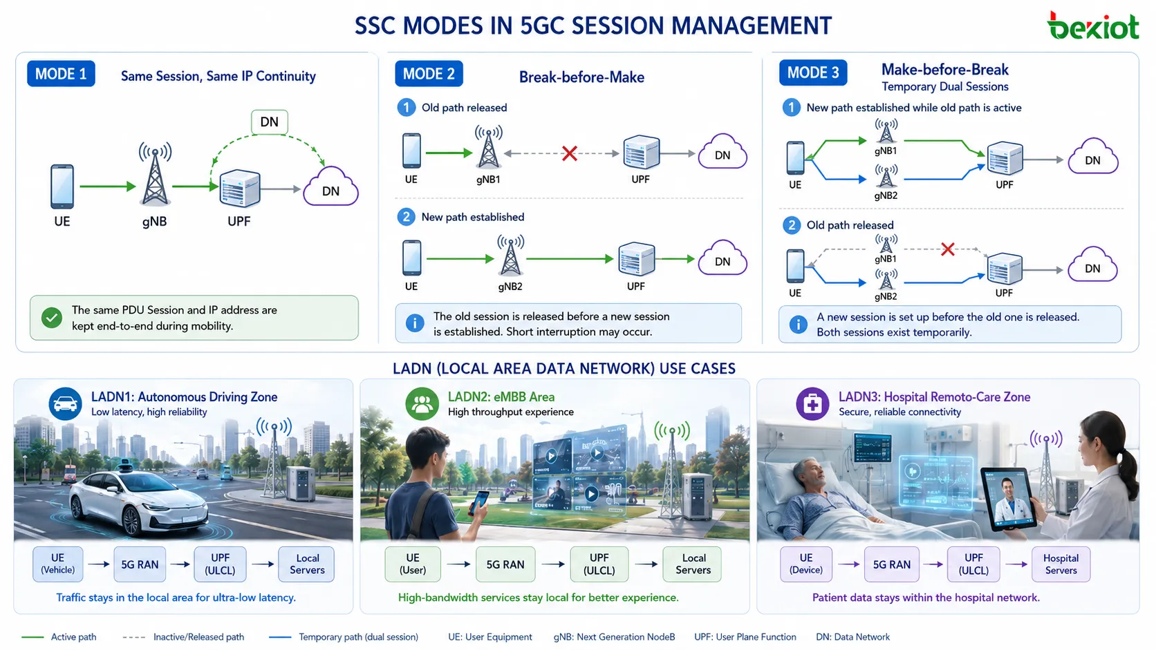
SSC means Session and Service Continuity. The phrase contains two related but different ideas. Session continuity means the PDU session and the UE IP address remain unchanged. Service continuity means the user experience remains continuous from the application perspective. A user watching video, making a voice call or using an interactive service may care most about whether the service is interrupted, while the network also needs to know whether the same session and IP address are preserved.
SSC Mode defines how the network handles continuity when UE movement triggers a change in path, anchor or service access. 5G defines three SSC modes. Each mode gives a different balance between session continuity, service continuity and user-plane flexibility.
SSC Mode 1
SSC Mode 1 preserves both session continuity and service continuity. The same PDU session is maintained, and the UE IP address does not change. This is the strongest continuity option and is required for services where disruption is unacceptable. VoNR is a typical example because voice service depends on stable continuity during mobility.
SSC Mode 2
SSC Mode 2 does not preserve session continuity, but it aims to preserve service continuity from the user experience perspective. It uses a break-before-make approach. The old PDU session is released before the new session is established. This can be acceptable for some services, but from the user experience perspective it is weaker than the other options.
SSC Mode 3
SSC Mode 3 also does not preserve the same session continuity, but it uses a make-before-break approach. A new PDU session is established before the old one is released. During the transition, the UE may temporarily maintain two PDU sessions. This makes the user experience better than SSC Mode 2 in many cases because service interruption can be reduced.
From the user experience perspective, SSC Mode 1 provides the strongest continuity, SSC Mode 3 is generally better than SSC Mode 2, and SSC Mode 2 is the least favorable of the three. The choice belongs to SMF and is based on the UE request, subscription data and allowed mode set. Once the session is established, the SSC Mode remains fixed for that PDU session.
LADN Limits Local Reach
LADN stands for Local Area Data Network. It represents a data network service that is only available inside a specific service area. The area is made of one or more Tracking Areas. When the UE is inside the LADN area, it may access the related DNN if subscription and configuration allow it. When the UE leaves the LADN area, it cannot access that DN’s 5G service.
LADN is useful because some services are meaningful only in a local region. An autonomous driving service may be available only inside a test zone. A remote healthcare service may be tied to a hospital area. A factory application may be valid only inside a private industrial campus. In these cases, the data network is not a global mobile internet service. It is a local service with location-dependent availability.
The UE and the network both need LADN-related awareness. The UE can be configured to know whether a DNN is an LADN DNN and which application is associated with that LADN DNN. The service area and LADN DNN are configured in AMF on a per-DN basis. AMF can provide LADN information to the UE during registration or configuration update procedures.
LADN has three location states from the session management perspective. In means the UE is inside the LADN area. Out means the UE has left the LADN area. Unknown can apply when the UE is in a state such as CM-IDLE and the network does not have a precise current indication. SMF can use information from AMF to determine whether the UE is still inside the service area.
If the UE is outside the LADN service area, it should not request user-plane activation for that LADN DNN and should not request PDU session establishment or modification for that DNN. If the UE has no LADN service area information for a LADN DNN, it should consider itself outside the LADN service area. When SMF receives an LADN-related session request and does not receive a valid indication that the UE is inside the service area, it treats the UE as outside and rejects the request.
Edge Paths Need Anchors
Edge computing support is one of the reasons 5GC session management needs a more flexible user-plane design. A service may require some traffic to go to a remote server and other traffic to stay local. For example, ordinary logs may be sent toward a remote data center, while low-latency control traffic may be routed to a local application server near the access network.
The concept of PSA, or PDU Session Anchor, is important here. A PSA is a UPF that anchors a PDU session and provides an N6 interface toward the data network. Not every UPF is automatically a PSA. Some UPFs may serve other roles, such as classification or forwarding. The user-plane design depends on how UPFs are arranged and how traffic should reach local or remote DNs.
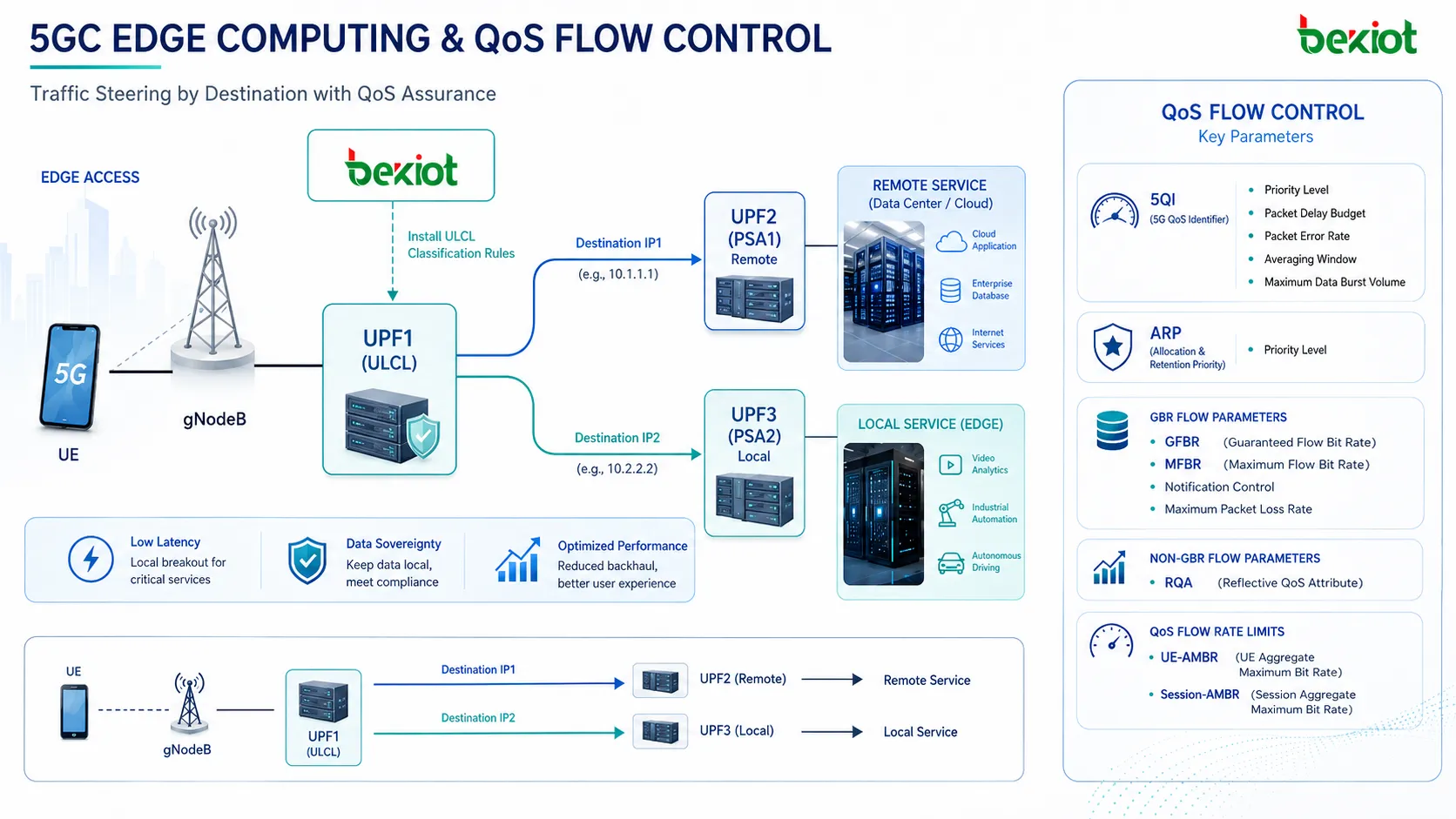
Two steering methods are important. ULCL, or Uplink Classifier, classifies uplink traffic based on rules. It can be used for IPv4 and IPv6 traffic. SMF can install ULCL rules so that traffic matching a specific destination or service class is sent toward the correct branch. For example, traffic toward one destination may be sent to a remote server, while traffic toward another destination is sent to a local edge service.
The second method is the Branching Point approach, which is based on IPv6 prefix branching. This method applies only to IPv6. It allows traffic steering according to IPv6 prefix logic, making it suitable for designs where IPv6 addressing can identify local or remote service branches.
These mechanisms make edge computing practical inside 5GC session management. SMF controls the session rules, UPF handles packet forwarding and classification, and PSA provides the anchor toward the DN. The result is a service path that can be shaped according to traffic type rather than sending all traffic through a single distant core anchor.
QoS Flow Adds Granularity
QoS Flow is the main QoS control granularity in 5G. Instead of using EPS bearers as the central service differentiation unit, 5G uses QoS Flows identified by QFI. Each QoS Flow can carry its own QoS profile and can be mapped to a DRB by gNB. The number of DRBs does not need to equal the number of QFIs. gNB can decide whether multiple QoS Flows are mapped to the same DRB or different DRBs according to radio conditions and policy.
A typical service example can include ordinary internet applications, cooperative service traffic and operator-owned services. General app traffic may use a non-GBR QoS Flow. More demanding traffic, such as real-time VR, AR or gaming-related service, may use a GBR QoS Flow. VoNR audio and video may use different GBR QoS Flows with service-specific 5QI values. This gives the network a more detailed way to treat different service flows.
QoS parameters are organized at several levels. At the QoS Flow level, common parameters include 5QI and ARP. 5QI relates to characteristics such as priority level, packet delay budget, packet error rate, averaging window and maximum data burst volume. ARP helps determine allocation and retention priority when resources are limited.
GBR Flow parameters include GFBR, or Guaranteed Flow Bit Rate, and MFBR, or Maximum Flow Bit Rate. These are mandatory for GBR flows. Notification control and maximum packet loss rate can also appear as optional parameters. For Non-GBR flows, RQA, or Reflective QoS Attribute, may be used. At a broader limit level, UE-AMBR and Session-AMBR control aggregate bit rate behavior for non-GBR traffic.
This granularity is one of the major differences between 4G bearer logic and 5G session logic. In 4G VoLTE, default and dedicated bearers were associated with APN, QCI, EBI, E-RAB, DRB and user-plane tunnels. In 5G, PDU session, QFI, QoS Flow type, N3 tunnel and DRB mapping provide a different structure. The result is more flexible but also more dependent on correct SMF policy, QoS rule installation and gNB mapping behavior.
How Sessions Are Built
A PDU session is not established in isolation. The network needs several decisions before the user plane becomes usable. The UE requests a session using DNN, PDU session type and related parameters. AMF carries the NAS-SM message toward SMF. SMF checks subscription data, policy, slicing information and DNN configuration. It then chooses user-plane resources, assigns QoS rules and controls how the session should be connected to the DN.
The process can be understood as a sequence of decisions. First, the network checks whether the UE is allowed to use the requested DNN. Second, it checks whether the requested PDU session type is allowed. Third, it considers slice information through S-NSSAI. Fourth, it selects or confirms SSC Mode. Fifth, it decides which UPF or anchor path should be used. Sixth, it applies QoS and rate-control information.
The result is a session that is more than a tunnel. It contains service identity, data-network identity, user-plane path, QoS rules, continuity behavior, charging characteristics and possible area restrictions. If the session is related to a local service, LADN rules may apply. If the session is related to edge computing, PSA and ULCL behavior may apply. If the session is related to voice, IMS and QoS Flow behavior become critical.
Session modification can also occur after establishment. A QoS Flow may be added or modified. User-plane resources may be activated or deactivated. A session may be released when no longer needed, when the UE leaves a service area, or when policy requires it. Because SMF controls the session, it is the key function that turns subscription and policy rules into real data-path behavior.
This explains why troubleshooting 5GC session issues requires looking at more than radio access. Engineers may need to review AMF forwarding behavior, SMF selection, UDM data, DNN configuration, S-NSSAI, UPF path, QoS rule installation, LADN presence, SSC Mode and N4 rules toward UPF. A failure in any of these areas can make the session fail, behave incorrectly or lose the expected QoS treatment.
Planning Notes For Engineers
Good 5GC session management planning starts with service separation. Not every service should be forced into the same DNN, same slice, same QoS model and same continuity mode. Internet access, IMS, enterprise private access, local campus applications, industrial control traffic and edge services may have different requirements. A clean design should identify these differences before configuring DNN and subscription data.
The next priority is deciding how much session continuity is required. Some services need a stable UE IP address and uninterrupted session behavior. Others can tolerate a new session as long as the application recovers. Some services benefit from make-before-break, while others can accept break-before-make. SSC Mode should be treated as a service design choice, not just a parameter in a table.
LADN planning should begin with service geography. The service area must be built from Tracking Areas, and AMF must be configured with LADN DNN and service area information on a per-DN basis. The UE also needs the correct local configuration so it can understand whether a DNN is a LADN DNN and which application should use it. If LADN service area information is missing, the UE should treat itself as outside the area, which can cause service attempts to fail as designed.
Edge planning needs clear traffic steering logic. ULCL rules should match real application traffic, not vague service assumptions. If local traffic and remote traffic are mixed inside one PDU session, SMF and UPF behavior must be configured carefully. PSA selection, N6 connectivity, N9 paths and local server placement all affect latency and service continuity.
QoS planning needs equal attention. It is not enough to define a 5QI value. Engineers should understand whether the flow is GBR or Non-GBR, whether GFBR and MFBR are required, whether Session-AMBR and UE-AMBR are appropriate, how QFI is assigned, and how gNB maps QoS Flows to DRBs. If the radio mapping does not align with service expectations, the session may be correctly established but still deliver poor experience.
Finally, session management should be tested with realistic movement and service scenarios. A static lab call does not prove SSC behavior. A single internet session does not prove LADN restriction. A simple throughput test does not prove QoS Flow differentiation. Engineers should test registration without session establishment, multiple PDU sessions, LADN entry and exit, SSC Mode behavior, edge breakout, QoS Flow addition, user-plane activation and session release.
Final Technical View
5GC session management is the part of the core network that turns service intent into data connectivity. It creates and controls PDU sessions, selects DNN access, applies slice and subscription rules, chooses SSC Mode, manages UPF paths, supports local-area restrictions and assigns QoS Flow treatment. It gives 5G the flexibility needed for smartphones, voice services, industrial devices, enterprise networks, local access and edge computing.
The move from 4G bearer logic to 5G PDU session logic is not just a terminology update. It changes how connectivity is created, how services are separated, how QoS is applied and how user-plane paths are steered. AMF and SMF separation makes the architecture more modular. UDM subscription data becomes more structured. SSC Mode gives the network different continuity models. LADN adds area-based service access. ULCL and PSA enable edge paths. QoS Flow replaces bearer-centered thinking with finer service classification.
The strongest way to understand 5GC session management is to follow a service from request to user plane. The UE asks for a PDU session. AMF carries the session message. SMF checks subscription, DNN, slice, PDU type and SSC Mode. UPF creates the path toward the DN. QoS rules classify traffic. gNB maps QoS Flows to radio bearers. Mobility and location changes then influence continuity, local service access and edge routing. Each step is part of the same session management chain.
FAQ
Why can a UE register without creating a PDU session?
Registration only tells the network that the UE is known and reachable. A PDU session is only needed when user data service is required, so 5G can avoid creating user-plane resources before they are useful.
Why does AMF forward NAS-SM messages instead of processing them fully?
AMF is designed around access and mobility control, while SMF owns the session logic. Forwarding NAS-SM signaling keeps these responsibilities separated and makes the architecture more modular.
What makes DNN more than a renamed APN?
DNN is tied to 5G session rules, slice context, PDU session types, LADN behavior, policy control and SMF selection, so it carries a broader role than a simple access name.
When should SSC Mode 3 be preferred over SSC Mode 2?
SSC Mode 3 is useful when a service can tolerate a changed session but benefits from make-before-break behavior, reducing interruption compared with releasing the old session first.
Why does LADN require UE-side awareness?
The UE needs to know whether a DNN is a LADN DNN and whether it is inside the configured service area before requesting session establishment, modification or user-plane activation.