
The real challenge in a multi-PCF deployment is not the existence of multiple PCF instances itself. The problem is that the same UE can easily be routed to different PCFs during different service procedures. During PDU session establishment, the SMF may already have established a policy association with one PCF. Later, when an IMS voice service is triggered and the AF initiates a new policy request, load balancing may send that request to another PCF. Once that happens, the policy context between the two stages is broken, which can lead to inconsistencies in VoNR QoS flows, PCC rules, and session policies.
BSF, or Binding Support Function, is specifically designed to solve this type of problem where requests for the same user across different interfaces need to reach the same PCF. It does not generate PCC rules and does not replace the PCF in making policy decisions. Its core responsibility is to maintain the binding relationship between a UE session and its associated PCF, allowing service consumers to locate the PCF that has already participated in policy control for that user when subsequent requests arrive.
Why Multi-PCF Networks Can Select the Wrong PCF
To understand the value of the BSF, it helps to look back at a similar issue that already existed in 4G. In the EPC architecture, the PGW communicates with the PCRF over the Gx interface, while the P-CSCF in the IMS domain sends policy authorization requests over the Rx interface. When multiple PCRFs are deployed, the Gx and Rx signaling paths must ultimately reach the same PCRF. Otherwise, later IMS service requests cannot inherit the policy context created earlier in the session.
In 4G networks, the common solution is to use a DRA for Diameter routing and session binding. Consider a typical case: when the PGW establishes a PDN connection for the IMS APN, the Gx request is routed through DRA1 to PCRF1. DRA1 records the relationship between the IMSI, UE IP address, and PCRF1. If a later Rx message from the P-CSCF is sent to DRA2 because of load balancing, and DRA2 forwards the request to PCRF2, PCRF2 has no knowledge of the session context previously established on the PGW side.
The impact is much more serious than simply selecting the wrong server. PCRF2 does not have the existing PCC rule state, so new media policy requests received over Rx cannot be properly correlated with the policies previously established over Gx. In 4G deployments, this problem can be addressed by synchronizing binding information in real time between multiple DRAs, but such implementations are often vendor-specific, making multi-vendor deployment and long-term operations significantly more complicated.
In 5GC, the requirement for policy consistency remains the same, although the network functions and interfaces have changed. The SMF communicates with the PCF over N7, while the AF requests policy authorization over N5. In a complete VoNR policy flow, the AF first provides application-flow and QoS requirements, the PCF generates the corresponding PCC rules, and the SMF and UPF then enforce those rules. If different requests for the same UE reach different PCFs, policy continuity can still be broken.
The BSF effectively standardizes a binding capability that previously depended on proprietary synchronization mechanisms. It maintains the relationship between the current UE session and the responsible PCF, helping ensure that later policy requests are routed back to the PCF instance that has already participated in the session.

What Information Does the BSF Bind?
From an implementation perspective, the BSF can be viewed as a dynamically maintained UE-to-policy ownership table. After a PCF becomes involved in policy control for a UE's PDU session, it registers the required binding information with the BSF. Other network functions can later query the BSF using UE identifiers and session characteristics to retrieve the corresponding PCF addressing information.
A typical binding record may include the UE IP address, SUPI, DNN, S-NSSAI, and the address of the associated PCF. In deployments that need to interwork with traditional Diameter interfaces, the record may also include the PCF's Diameter host name or FQDN.
These fields are not simply collected for completeness. Each one has a specific role in filtering and identifying the correct binding:
UE IP: Provides a direct way to locate the binding based on the current user-plane address and is one of the most common query parameters.
SUPI: Identifies the subscriber at the user-identity level and helps ensure that the binding is associated with the correct UE.
DNN: Distinguishes different data networks used by the same UE, such as IMS and regular Internet services.
S-NSSAI: Further identifies the network slice associated with the session in a sliced 5G deployment.
PCF Address: Provides the actual addressing information required by a service consumer to reach the selected PCF.
Diameter Host Name/FQDN: Provides a mapping reference for traditional Diameter routing in deployments where SBI and Diameter coexist.
For this reason, BSF binding should not be reduced to a simple one-to-one mapping between a UE address and a PCF address. A single UE can have multiple PDU sessions and may access different DNNs or network slices. If the query conditions are too broad, the returned PCF may not match the current service context.
In deployment, the granularity of the binding should match the granularity of policy control. This is especially important for IMS services, where policy continuity is critical. If the UE has multiple slices or multiple data-network contexts, DNN and S-NSSAI should not be omitted from the binding criteria.
How Should Nbsf_Management Be Used?
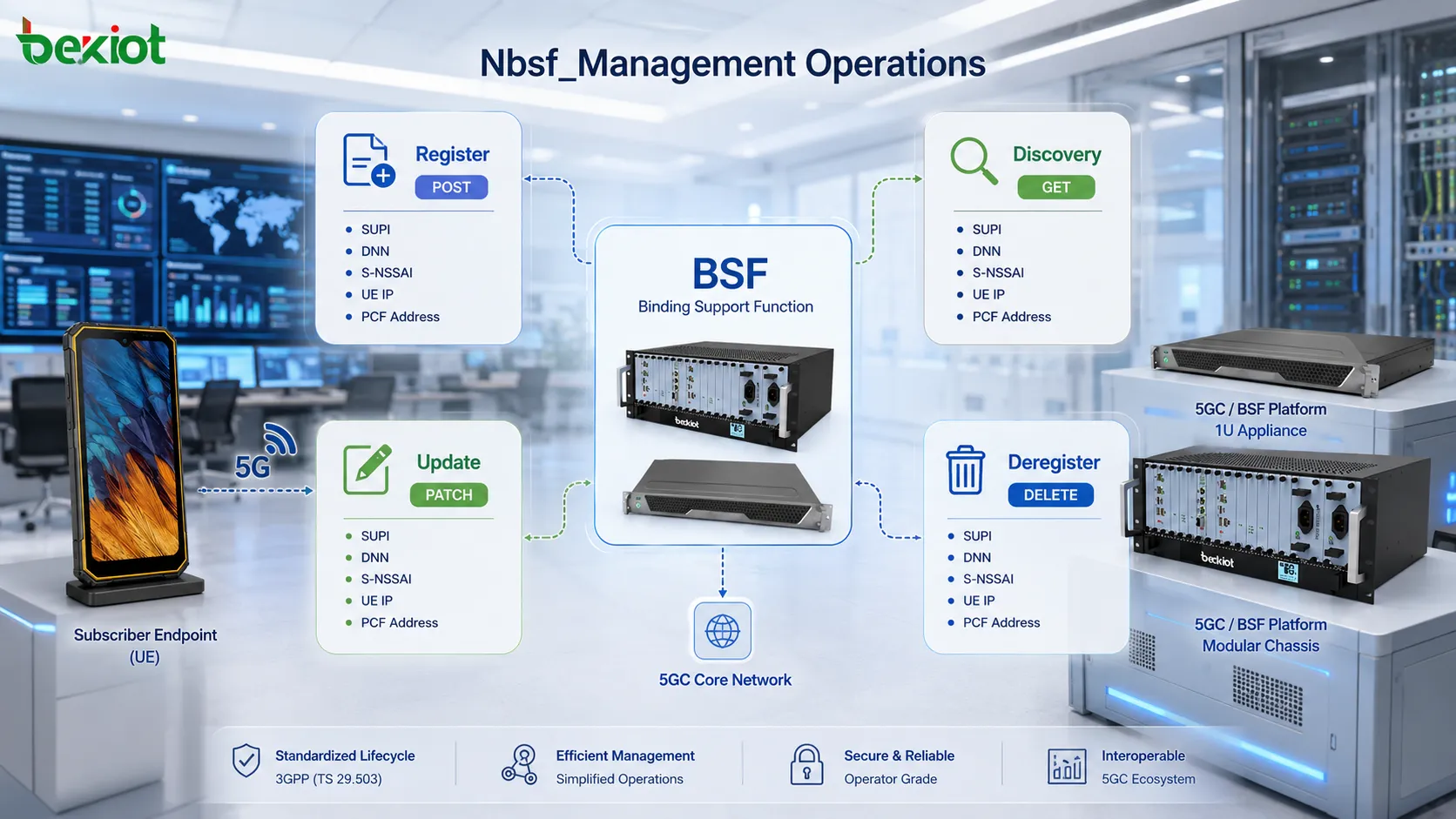
The BSF exposes the Nbsf_Management service over SBI. The service is not built around a large collection of unrelated APIs. Instead, it provides four core operations covering the complete lifecycle of a binding record: registration, discovery, update, and deregistration. In practical deployments, these four operations can be mapped directly to the creation, use, maintenance, and removal of a PCF binding.
Register: Create the Binding First
Once a PCF has been selected and becomes involved in policy control for the UE, it needs to register the binding with the BSF. A typical request is:
POST .../pcfBindings
The request body can include key fields such as the UE IP address, SUPI, DNN, S-NSSAI, PCF address, and the corresponding FQDN. After the BSF successfully creates the binding record, it returns:
201 Created
Timing is one of the most common implementation pitfalls at this stage. The binding must be registered before any later service-side query is initiated. Otherwise, when an AF-side request or a Diameter-compatible request reaches the network, the BSF may not yet have a corresponding PCF binding, causing the lookup to fail.
Discovery: Retrieve the Existing PCF from the Session Context
The Discovery operation is where the practical value of the BSF becomes most visible. A service consumer sends a query using the UE information currently available:
GET .../pcfBindings?query_parameters
The query parameters can include the UE IP address, SUPI or GPSI, DNN, S-NSSAI, and other relevant identifiers. If a matching binding is found, the BSF returns:
200 OK
The response includes the corresponding PCF address and, where necessary, the Diameter host name or FQDN. In the standardized architecture, service consumers may include functions such as the NEF, AF, and NWDAF. In deployments that still need to support traditional Rx routing, the returned binding information can also be used to select the correct PCF for subsequent signaling.
Update and Deregister: Maintain the Binding Lifecycle
If the binding information changes, an existing record can be updated using PATCH:
PATCH .../pcfBindings/{bindingId}A successful update returns 200 OK. When the session is released, the PCF no longer serves the UE, or the binding becomes invalid, the record should be deleted using:
DELETE .../pcfBindings/{bindingId}A successful deletion normally returns 204 No Content. In real deployments, the deregistration step should not be ignored. If stale binding records remain in the BSF for too long, the same subscriber may later establish a new session and accidentally match an outdated PCF. This type of issue is often more difficult to troubleshoot than a simple missing binding.
How to Troubleshoot N7 and Rx Binding
Across the full signaling path, the BSF workflow can be divided into three stages: first register the binding, then query the binding, and finally route subsequent policy signaling back to the original PCF. Once this sequence is clear, troubleshooting VoNR policy issues becomes much more efficient than simply collecting large amounts of signaling without a clear direction.
Stage One: Establish the PDU Session and Register the PCF
After a BSF instance comes online, it first registers its capabilities and addressing information with the NRF. The UE then establishes a PDU session for the IMS DNN, and the SMF requests policy control from a PCF. Once the PCF has been selected, it invokes Nbsf_Management_Register to store the UE-to-PCF binding in the BSF.
At this point, the BSF may contain binding records similar to:
UE IP1 + DNN1 + S-NSSAI1 + SUPIxx → PCF1
UE IP2 + DNN2 + S-NSSAI2 + SUPIyy → PCF2
Stage Two: A VoNR Call Triggers a Policy Lookup
When the UE initiates a VoNR call, the IMS domain triggers a new policy authorization request. In the standardized 5GC architecture, the AF and PCF exchange policy information over the N5 interface. In some deployments that continue to use traditional IMS Diameter signaling, the P-CSCF may still use the Rx/AAR procedure.
The key question at this stage is straightforward: which PCF should receive the policy request?
The requester should not simply select another PCF according to ordinary load-balancing logic. Instead, it first queries the BSF using information such as the UE address, DNN, and S-NSSAI. The BSF matches the existing binding record and returns the PCF instance already responsible for the UE session.
Stage Three: Route Subsequent Signaling Back to the Original PCF
Once the correct PCF has been identified, subsequent policy requests are directed to that same PCF. This keeps the policy context created during PDU session establishment and the new policy requests generated during the VoNR media stage on the same policy-control instance. The PCF can then generate and maintain PCC rules using the complete session context.

If a VoNR call can be initiated but QoS policy behavior is abnormal, IMS media rules are inconsistent, or only some subscribers experience intermittent failures, the BSF binding path should be checked before immediately attributing the problem to the radio network.
A practical troubleshooting sequence can be divided into four steps. First, confirm that the BSF Register operation was actually performed after PDU session establishment. Second, verify that the UE IP address, SUPI, DNN, and S-NSSAI stored in the BSF are correct. Third, check whether the query conditions used in the later Discovery request can uniquely match the original binding. Fourth, verify that the returned PCF address or Diameter identifier is exactly the same as the PCF that originally participated in N7 policy control.
Deployment architecture also needs to be considered. In some networks, the BSF may be co-located with the SMF. In that case, packet-capture points and internal call flows may differ from those in a standalone BSF deployment. However, the fundamental principle remains unchanged: the network must maintain a stable binding between the UE session and the responsible PCF.
Frequently Asked Questions
Do the BSF and NRF Both Perform Network Function Selection?
No. Their roles are different. The NRF helps network functions discover available NF instances and their capabilities, acting more like a service registry. The BSF stores an already established binding between a specific UE session and a PCF. In simple terms, the NRF answers, “Which PCFs are available?” while the BSF answers, “Which PCF is already responsible for this UE session?”
Can a UE Have Only One PCF Binding?
Not necessarily. A binding is not defined solely by the UE identity. It can also depend on the DNN, S-NSSAI, and the specific PDU session context. If the same UE accesses different data networks or network slices, the corresponding bindings may need to be maintained separately.
Can the BSF and SMF Be Deployed in the Same Network Function Instance?
Yes. A co-located deployment is possible. In that case, the externally visible signaling sequence may differ from a standalone BSF deployment, but the UE-to-PCF binding still needs to be stored and used. During troubleshooting, the actual vendor deployment architecture should therefore be confirmed first.
What Should Be Checked First When a BSF Query Fails?
Start with three items: whether the binding record was successfully created, whether the query parameters match the values used during registration, and whether the binding has expired or been deleted prematurely. If the BSF does return a record, also verify that the returned PCF address, FQDN, or Diameter identifier points to the expected PCF instance.