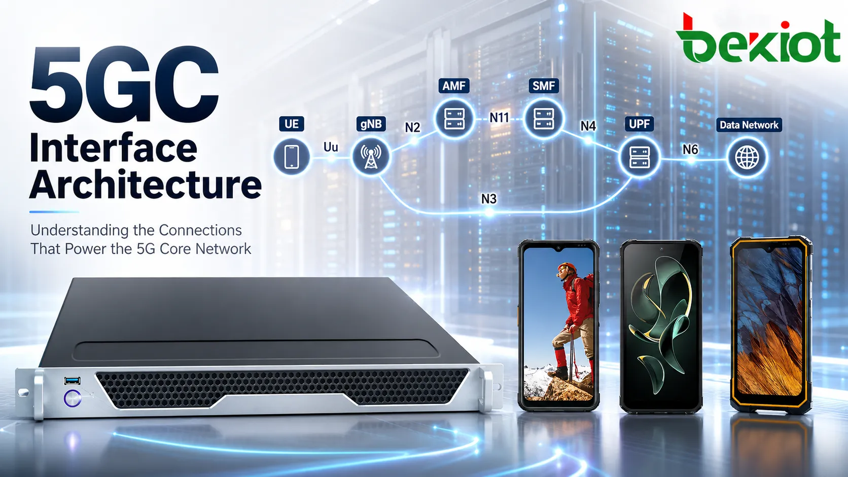
When engineers first encounter 5G Core interfaces, it is common to start by memorizing everything from N1 to N50: the network functions at both ends, the protocol used, and the closest equivalent in 4G. That approach may help at the beginning, but it quickly becomes insufficient during deployment, signaling analysis, and troubleshooting. In practice, the more useful questions are: Does this interface belong to access, session management, policy control, or the user plane? Does it carry NAS, GTP-U, PFCP, or an SBI service? And when a problem occurs, which control path should be followed next?
The key to understanding 5GC interfaces is not memorizing interface numbers, but identifying the communication layer and function each interface belongs to.
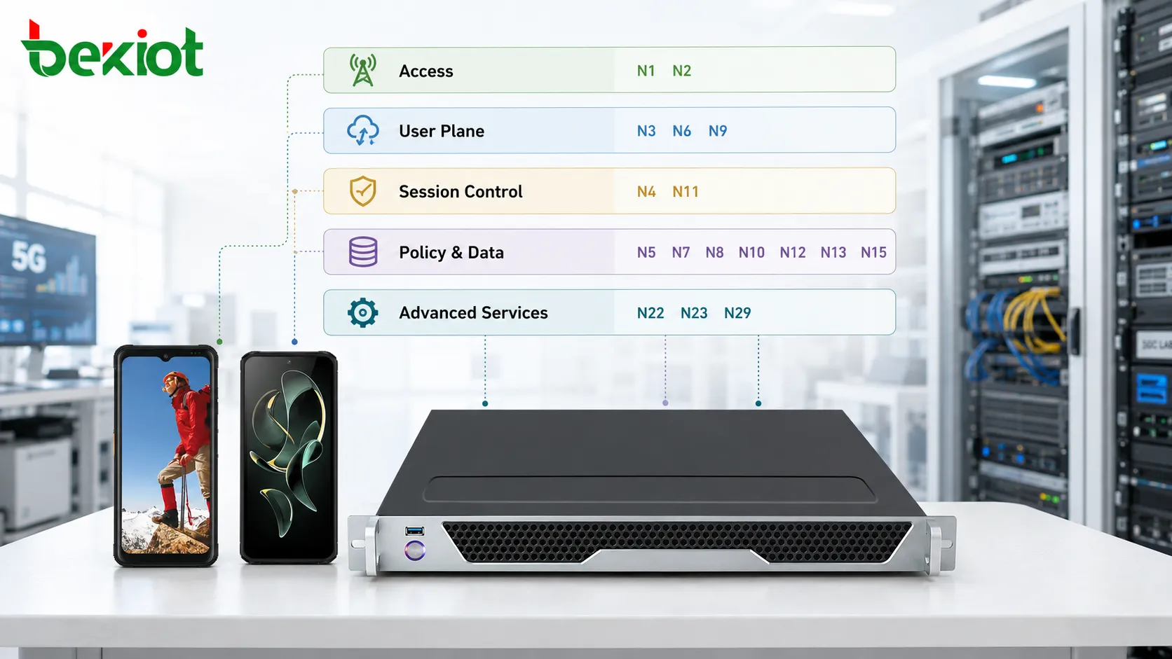
UE access and access control mainly involve N1 and N2;
User-plane traffic mainly travels over N3, N6, and N9;
SMF and UPF use N4 for user-plane control;
Policy, subscription, authentication, and network slicing functions are increasingly implemented through HTTP/2-based SBI services.
This is also one of the most important architectural differences between 5GC and EPC. 5G does not simply rename interfaces such as S1, S11, Gx, and S6a. Instead, it retains a number of reference-point interfaces while introducing the Service-Based Architecture, or SBA, allowing control-plane network functions to interact through service calls. For this reason, 5GC interfaces are best analyzed from both the reference-point perspective and the SBA service perspective.
How to Understand SBA and Reference-Point Architecture
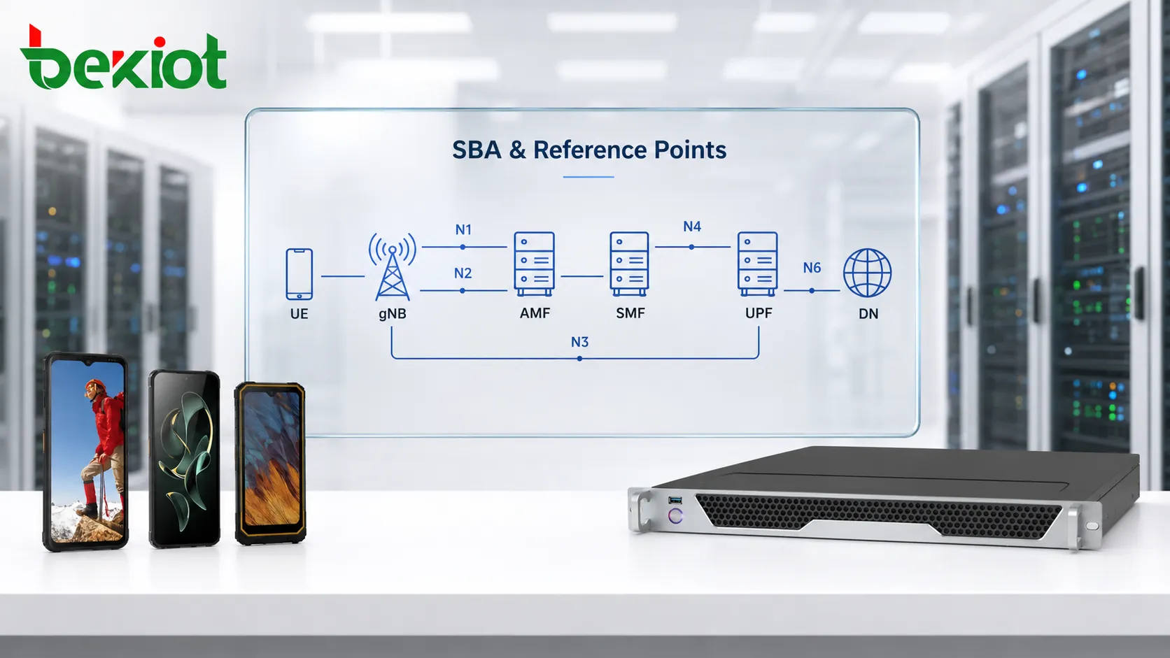
There are two useful ways to view 5GC. The first is the traditional reference-point architecture, which describes the logical relationship between two functional entities, such as N1 between the UE and AMF, N2 between the gNB and AMF, N3 between the gNB and UPF, and N4 between the SMF and UPF. The second is the SBA view, where control-plane functions such as AMF, SMF, PCF, UDM, AUSF, NSSF, NEF, and NRF are treated as service producers and service consumers.
These two views are not contradictory. The reference-point model is useful for tracing end-to-end signaling paths, while SBA provides a clearer way to understand dynamic network-function discovery, service invocation, and service expansion.
N2, for example, has a very clear endpoint relationship: the gNB connects to the AMF and uses NGAP to transport NAS signaling and support connection management. N3 connects the gNB to the UPF and carries user-plane traffic through GTP-U. Interfaces of this type have a clear point-to-point path characteristic.
When the AMF accesses the UDM, AUSF, or PCF, however, the focus shifts toward the services exposed by those network functions. N8 is used between the AMF and UDM to obtain mobility-management subscription information, N12 supports authentication management between the AMF and AUSF, and N15 allows the AMF to obtain mobility-related policies. These relationships reflect the migration of the 5GC control plane from traditional dedicated protocols toward HTTP/2-based service interactions.
This means that when analyzing packet captures or architecture diagrams, engineers should not treat an interface such as N8 as merely a fixed physical connection. It is more important to determine which NF is consuming which service, how the service instance was discovered, and which stage of the service procedure the HTTP/2 transaction belongs to.
How Can Core Interfaces Be Grouped?
Instead of memorizing interface numbers one by one, a more practical method is to group them according to the network function they support. When a signaling message appears, engineers can first identify the functional category and then narrow the analysis down to the specific interface.
Access and User-Plane Paths
N1, N2, and N3 form the most fundamental interface group on the 5G access side. N1 operates between the UE and AMF and carries mobility-management and session-management information in 5G NAS. N2 connects the gNB and AMF, uses NGAP to transport NAS signaling, and supports connection management. N3 connects the gNB and UPF and carries actual user-plane traffic through GTP-U.
Within the core network, UPFs can continue forwarding user traffic over N9 using GTP-U, while the UPF connects to the external Data Network, or DN, through N6. Traffic on N6 is no longer 5G-specific control signaling; it is application-layer IP traffic such as web content, images, video, and other user data.
Therefore, if UE registration succeeds and the PDU session is established but application traffic still cannot pass, troubleshooting should usually move away from the AMF control plane and toward N3, UPF forwarding behavior, N6, and the external DN.
Session and User-Plane Control
N4 is one of the most important control interfaces in 5GC. It operates between the SMF and UPF and uses PFCP. The SMF manages session control, while the UPF performs packet forwarding, so N4 is the interface used to install forwarding rules and control user-plane behavior.
N11 connects the AMF and SMF and mainly supports PDU session-management signaling. When a UE initiates PDU Session Establishment, the AMF passes the session-management request to the SMF for further processing. If registration succeeds but PDU session establishment fails, N11 and the subsequent SMF procedures are usually important troubleshooting points.
N16 supports interactions between SMF instances, including SMF reselection-related procedures. Compared with EPC, 5GC separates control functions into a larger number of independent NFs. Responsibilities that were previously concentrated in the MME, SGW, or PGW are distributed across functions such as AMF, SMF, PCF, and UDM, creating new service relationships.
Policy, Authentication, and Subscription Data
Policy control is largely centered on the PCF. N7 connects the SMF and PCF and is used to request session-management-related policies. N5 operates between the PCF and AF and carries application-level service parameters and requirements. N15 allows the AMF to obtain mobility-related policies.
For subscriber data, N8 allows the AMF to access the UDM and retrieve mobility-management subscription information, while N10 connects the SMF and UDM to obtain session-management-related subscription data. Authentication is further separated into N12 between the AMF and AUSF and N13 between the AUSF and UDM.
This separation is particularly important. In EPC, the HSS handled a large portion of subscriber and authentication data functions. In 5GC, responsibilities are divided more precisely across UDM, AUSF, and related data-storage functions. When authentication fails, checking only whether subscriber data exists is no longer sufficient. Engineers also need to determine whether the failure occurred when the AMF initiated authentication, during AUSF processing, or when the AUSF attempted to retrieve the required information from the UDM.
What Do Advanced Service Interfaces Handle?
The scalability of the 5GC interface model becomes especially clear beyond N1 through N16. As network slicing, capability exposure, network analytics, roaming, and data decoupling are introduced, more interfaces are established around independent network functions.
N22 connects the AMF and NSSF for network-slice selection. N34 connects the NSSF and NWDAF so that network analytics can support slice-related decisions. The NWDAF can also provide analytics information to the PCF through N23, allowing analytics data to assist policy decisions. As a result, policy control no longer needs to rely only on static subscription information and predefined rules.
Capability exposure mainly involves the NEF. N29 operates between the SMF and NEF, while N30 connects the NEF and PCF. N33 supports service invocation between APIs and the AF. The NEF therefore occupies an important position between external applications and core-network capabilities, providing a controlled way to expose network functions to application-side services.
Data storage is also further separated. N35 connects the UDM and UDR for subscription-data storage, N36 connects the PCF and UDR for policy-data storage, and N37 allows the NEF to access the UDR for capability-exposure and application-related data. UDSF is also used for unstructured data storage, supporting the separation of computing and storage functions.
In roaming and inter-operator scenarios, additional interfaces include N24 between the visited PCF and home PCF, N27 between the visited NRF and home NRF, N31 between the V-NSSF and H-NSSF, and N32 between the V-SEPP and H-SEPP. SEPP provides security control at inter-operator boundaries. These interfaces may not commonly appear in a single-operator local test environment, but they become important when analyzing roaming architectures.
Charging functions are also moving away from the traditional Diameter-based model toward service-based interactions. N28 connects the PCF and CHF so that charging-related information can support PCC rule decisions, while N40 connects the SMF and CHF. N41 through N49 are reserved within the relevant specification range. Another specialized interface is N50, which connects the AMF and CBCF for public warning and disaster-alert services.
What Should Be Considered When Mapping 5GC to EPC?
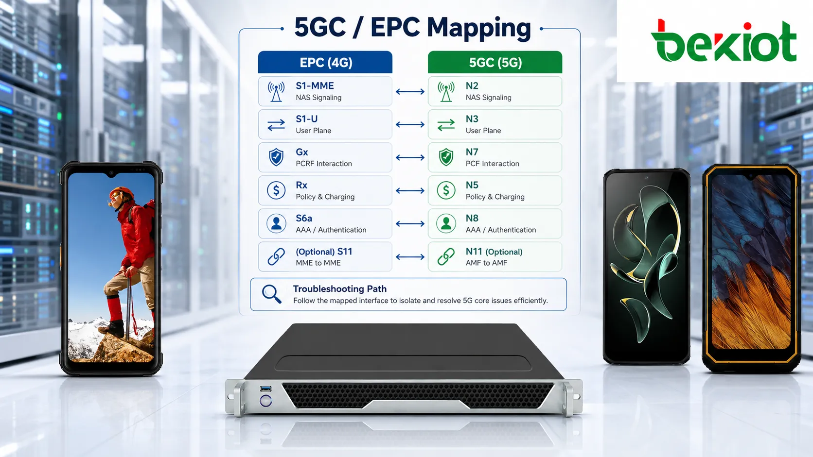
EPC experience is very useful when moving from 4G to 5G, but the relationship should not be treated as a mechanical one-to-one replacement. The similarities between 5GC and EPC interfaces are mainly functional references rather than exact equivalences.
Some mappings are relatively intuitive. N2 can be compared functionally with S1-MME, while N3 resembles S1-U. N4 is functionally similar to Sxa, Sxb, and Sxc in a CUPS-based EPC architecture. N7 can be compared with Gx from a policy-control perspective, while N5 helps explain the application-policy role traditionally associated with Rx.
Similar migration patterns can also be seen in subscriber and authentication functions. N8 can be functionally compared with part of the S6a interaction between the MME and HSS. N14, which supports mobility management between AMFs, can be compared with S10 between MMEs, while N17 for equipment identity checking corresponds functionally to the S13 interaction between the MME and EIR.
However, many 5GC interfaces have no direct 4G equivalent. Examples include N22 for slice selection, N23 for network analytics, N27 for cross-domain NRF discovery, and the interfaces surrounding UDR-based data storage. These relationships were introduced as a result of the service-based architecture and greater functional decoupling in 5GC.
A better migration method is therefore to compare functions first and signaling mechanisms second, rather than forcing every N interface to match an S interface or Diameter reference point. The protocol evolution is especially significant: EPC control-plane signaling relied heavily on Diameter and GTPv2, while many 5GC control-plane interactions now use HTTP/2-based SBI services.
A Practical Approach to 5GC Interface Analysis
In real 5GC signaling analysis, it is often more effective to work backward from the service symptom rather than forward from an interface number. If the UE cannot register, start with N1, N2, and the subsequent AMF authentication and subscriber-data procedures. If registration succeeds but the PDU session fails, continue with N11, the SMF, N7, N10, and N4. If the PDU session succeeds but user traffic cannot reach the data network, shift the focus to N3, UPF forwarding, and N6.
For policy-related issues, continue with N7 and the PCF-related signaling chain. For slice-selection problems, focus on N22 between the AMF and NSSF. For capability exposure or application-driven policy requirements, extend the analysis toward NEF, AF, and PCF-related interfaces. Once a four-layer mapping of “service stage — network function — interface — protocol” is established, the dozens of N interfaces become much easier to interpret.
From architecture study to live-network troubleshooting, the most important part of 5GC interface analysis is understanding the relationship between the functions. The access layer brings the UE into the core network, session management establishes the PDU Session, policy and subscription services determine how that session should be handled, the user plane carries the actual application traffic, and SBA enables the control-plane functions to cooperate through service-based interactions. Understanding this end-to-end logic provides more engineering value than simply memorizing a complete interface table.
Frequently Asked Questions
Does a Higher N-Interface Number Mean a Newer Function?
No. N-interface numbers are used to identify logical reference points and do not indicate technology generation, importance, or chronological order. N1, N2, and N3 are among the most fundamental 5GC interfaces, while higher-numbered interfaces include both newer functional relationships and reserved reference points.
Do All 5GC Control-Plane Interfaces Use HTTP/2?
No. Many SBA-related control-plane interactions use HTTP/2, but 5GC includes several other protocols. N2 uses NGAP, N3 and N9 use GTP-U, N4 uses PFCP, and communication between the UE and AMF also involves 5G NAS. Troubleshooting should therefore begin by identifying the interface type before selecting the appropriate protocol-analysis method.
Why Is the N-Interface Name Sometimes Missing from Packet Captures?
N-interface names represent logical reference points in the architecture. Packet captures normally display the actual protocol, such as HTTP/2, NGAP, PFCP, or GTP-U, together with the IP addresses of the communicating network functions. The logical N interface must therefore be identified from the roles of the two NFs and the service procedure being analyzed.
Does a 5GC Test Network Need to Deploy Every Defined Interface?
No. The interfaces that actually appear depend on the network scale, enabled services, and whether the deployment supports features such as roaming, network slicing, capability exposure, network analytics, or public warning services. Basic registration and data connectivity use only a subset of the complete 5GC interface framework.