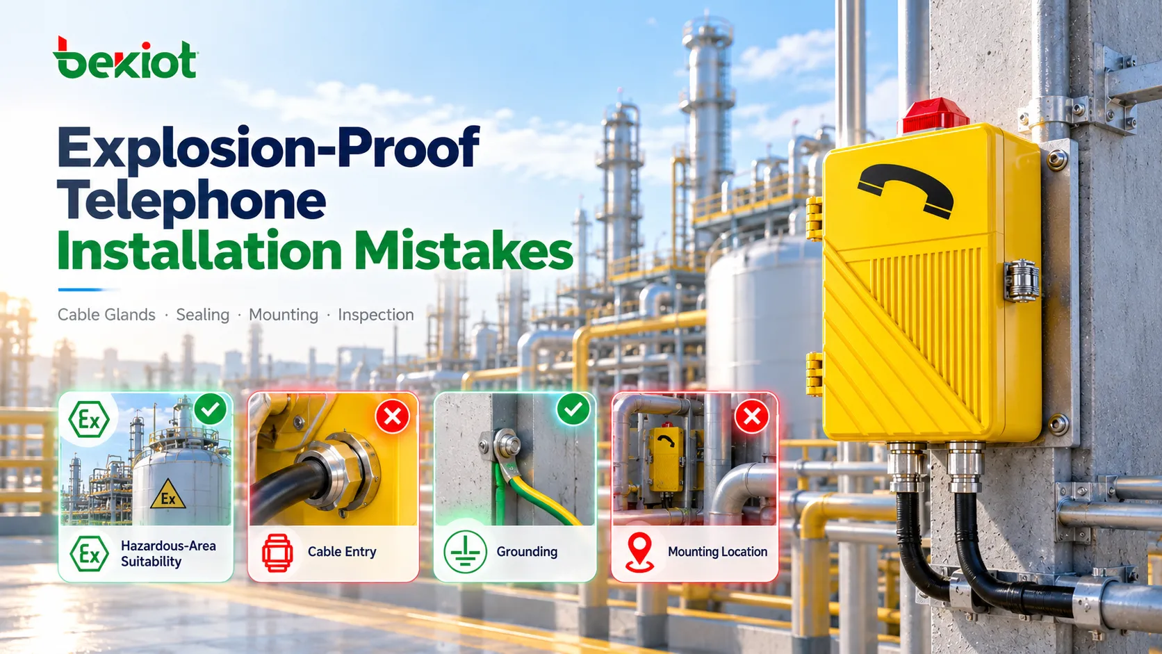
One situation can be especially misleading during the installation of an explosion-proof telephone: the device powers up, registers successfully with the SIP server, receives calls from the control room and can make outgoing calls without any obvious problem. From a communications perspective, everything appears to be working. Yet an installation detail may already have changed one of the controlled conditions on which the original equipment design depends.
A contractor may replace the specified Cable Gland with another model that happens to fit, close an unused entry with a convenient plug, drill a new opening because the original cable direction is difficult to use, or move the telephone several meters to simplify cabling. None of these actions necessarily causes an immediate communications failure. In fact, the telephone may still pass a basic call test on the same day. That is exactly why these mistakes are more difficult to identify than a device that simply refuses to power on.
For equipment installed in hazardous areas, successful communication only confirms that the communications path is currently working; it does not by itself confirm that the installation is correct. The enclosure design, actual mounting location, cable entry, blanking elements, accessories, power arrangement and initial inspection together define the final installed condition. IEC 60079-14:2024 places the design, selection, installation and initial inspection of Ex equipment within the same technical framework. In practical terms, selecting the correct equipment is only part of the engineering work.
Many of the most important installation risks appear during the relatively short period between taking the telephone out of its packaging and putting it into service on the wall.
Why Can a Telephone Work Normally and Still Be Installed Incorrectly?
For conventional low-voltage equipment, commissioning often follows a familiar sequence: power the device, connect it to the network and test its functions. If the terminal obtains an IP address, registers with the SIP server and completes incoming, outgoing and two-way voice calls, the installation may be considered nearly complete. An explosion-proof telephone cannot be evaluated only through this process because communications testing validates the service path, not the entire hazardous-area installation.
A Cable Gland, for example, may clamp the Ethernet cable securely enough for the telephone to come online. But if the gland is incompatible with the cable diameter, entry arrangement or explosion-protection concept, successful SIP registration does not eliminate the installation issue. In the same way, an enclosure that shows no immediate water ingress does not prove long-term environmental sealing, and a telephone firmly attached to a wall is not necessarily positioned where personnel can reach and operate it quickly during an emergency.
Several common assumptions create problems in hazardous-area communications projects:
Electrical continuity does not mean the explosion-protection installation is correct;
Successful SIP registration does not confirm that the cable entry has been installed correctly;
No visible water ingress does not guarantee reliable long-term environmental sealing;
Secure mechanical mounting does not guarantee that personnel can quickly locate and use the telephone during an incident.
Installation therefore needs to be evaluated along two parallel lines. The first is Explosion Protection Integrity: whether the installation has preserved the conditions associated with the equipment's original protection concept. The second is Emergency Communication Availability: whether the terminal remains accessible, usable and connected to the correct communications destination when it is actually needed. A fixed hazardous-area communications point has real engineering value only when both conditions are satisfied.
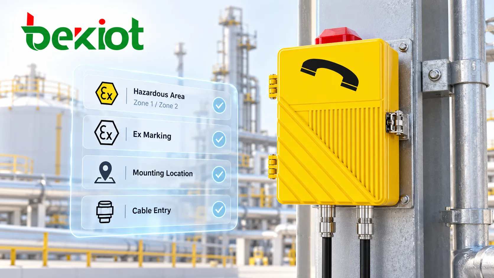
Mistake 1: Assuming Any Certified Explosion-Proof Telephone Can Be Installed Anywhere
“It is an explosion-proof telephone, so it can be installed anywhere in the hazardous area” is one of the simplest assumptions to make and one of the most important to avoid. Explosion protection is not a single generic category. Hazardous locations may involve gas or combustible dust, different zone classifications, equipment groups, temperature classes and ambient temperature conditions. Whether a device is suitable for a particular location depends on its actual Ex marking, certification scope and the standards applied to the project—not simply on the words “Explosion-Proof” in the product name.
This issue often appears late in a project. A telephone may have been assigned to Location A during design, but piping, structural steel, equipment, brackets or cable-routing constraints may cause installers to move it several meters during construction. For an ordinary IP phone, this may be little more than a site adjustment. For hazardous-area equipment, the new location needs to be checked to confirm that the same installation conditions still apply.
Moving the terminal therefore involves more than asking whether the Ethernet cable is long enough. The project should also confirm:
whether the hazardous-area classification is the same at the new location;
whether ambient temperature or corrosive exposure has changed;
whether the equipment marking and certification conditions remain applicable;
whether the cable route and entry arrangement still match the design;
whether the new position affects emergency access to the telephone.
If hazardous-area suitability has not yet been confirmed during equipment selection, refer to How to Select the Right Explosion-Proof Telephone for Hazardous Areas. During installation, the task is different: the conditions confirmed during design need to be preserved at the actual field location.
Mistake 2: Treating the Cable Gland as Nothing More Than a Cable Clamp
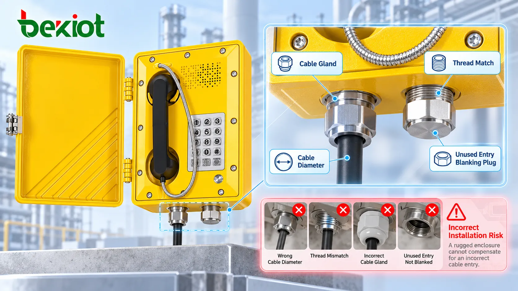
On an explosion-proof telephone, the Cable Gland is easy to overlook because it attracts far less attention than the telephone enclosure itself. Yet it is one of the most important areas to inspect. In a conventional low-voltage installation, a cable gland may mainly provide retention, environmental sealing and strain relief. In a hazardous-area installation, the cable entry also forms part of the conditions required to maintain the equipment's original protection concept.
IEC technical guidance for hazardous-area cable entries links Cable Glands directly to enclosure integrity and environmental protection. For equipment using an Ex “d” protection concept, the relationship between the cable and gland also affects whether the original flame-containment conditions are preserved. Installation therefore cannot be judged simply by whether the gland has been tightened.
At minimum, the site should verify:
whether the Cable Gland is suitable for the equipment's explosion-protection concept;
whether the thread specification matches the equipment entry;
whether the permitted cable diameter range matches the actual cable;
whether the gland is compatible with the cable construction when armored cable is used;
whether sealing components are correctly positioned, complete and not replaced with unsuitable parts;
whether the cable is exposed to continuous tension, side loading or mechanical compression.
Another common assumption is that a telephone with a high IP rating will automatically retain the same environmental protection after cabling. In reality, the factory enclosure condition and the field-installed cable entry are part of the same protection chain. A rugged enclosure cannot compensate for an incorrectly installed cable entry.
Mistake 3: Plugging Unused Entries with Whatever Fits and Drilling New Holes On Site
Temporary field solutions are common during construction: “We are not using this opening, so just plug it for now,” or “The original cable entry is difficult to reach, so drill another one.” These approaches may be acceptable for some ordinary enclosures, but they cannot automatically be applied to explosion-proof telephones.
Unused cable entries need to remain closed in a way that is compatible with the equipment design and installation requirements. A spare opening should not be sealed with an ordinary plastic plug, adhesive tape, temporary sealing compound or an unidentified threaded plug simply because no second cable is currently required. The same principle applies to field drilling: an explosion-proof enclosure should not be treated like a conventional stainless-steel or low-voltage junction box.
A new opening immediately raises several questions:
whether the additional entry is permitted by the original design and certification conditions;
whether the location, thread and wall thickness meet the applicable requirements;
whether the new Cable Gland forms a correct combination with the entry;
whether machining has changed the mechanical structure of the enclosure;
whether metal chips, burrs or machining damage have entered or affected the equipment.
If the project genuinely requires an Adapter, Reducer or a different cable-entry arrangement, the change should be checked against the equipment documentation, certification conditions, manufacturer requirements and the project's hazardous-area engineering rules. It should not be treated as routine field fabrication.
The same principle applies to enclosure joints, fasteners and sealing structures. Adding general-purpose sealant to a joint “for extra waterproofing,” or grinding a mating surface because the cover is difficult to close, may appear to solve a construction problem while introducing a new technical uncertainty.
Mistake 4: Choosing the Mounting Point Only for Cabling Convenience
In a hazardous area, cable length is easy to measure. The route a person must take to reach the telephone is much easier to overlook. On an engineering drawing, a telephone is represented by a coordinate. During a real incident, however, the user may be wearing a helmet, protective gloves, safety glasses and other PPE while working in a noisy, poorly lit environment surrounded by piping, steam or process equipment.
A telephone installed behind large equipment, across a narrow platform or away from a normal inspection route may technically be present while delivering much less practical emergency value. This becomes even more important for models fitted with horns, visual beacons or one-touch emergency calling because placement affects not only who can use the telephone, but also who can hear or see the associated alert.
The mounting location should therefore be reviewed from the user's perspective:
is the telephone easy to reach from normal inspection and operating routes;
would personnel need to cross a potentially hazardous area to reach it during an incident;
is the mounting height suitable for operating keys and lifting the handset while wearing gloves;
is the terminal obscured by piping, equipment or guardrails;
can it be identified quickly at night or under low-light conditions;
will continuous background noise interfere with ringing or two-way speech.
The best location for an explosion-proof telephone is not the point that is easiest to cable. It is the point that personnel can reach, recognize and use quickly when something goes wrong.

Mistake 5: Assuming PoE, Switches and Power Are Ordinary Low-Voltage Issues Once the Telephone Is Explosion-Proof
As SIP-based explosion-proof telephones have become more common, field installation has increasingly shifted from traditional telephone wiring toward a “single Ethernet cable” mindset. A PoE-powered SIP telephone may indeed have only one cable connected to the device, but that cable ultimately depends on a PoE switch, network cabinet, media converter, junction equipment, core network and SIP server or IP PBX. Any one of these elements can affect whether emergency communications remain available.
Treating PoE as “If the Network Is Up, the Phone Has Power”
PoE reduces the need for a separate power supply at the terminal, but it does not automatically provide backup power for the communications system. If the upstream PoE switch loses power, every dependent telephone may lose both power and network access. When explosion-proof telephones are used for emergency calling, the PoE switch, core network, SIP server and IP PBX should also be reviewed for UPS support, backup power and recovery arrangements.
Ignoring Installation Requirements for Other Network Equipment in the Hazardous Area
A telephone that is suitable for a hazardous area does not automatically make an ordinary switch, power module, junction device or network accessory suitable for the same location. Any electrical equipment physically installed in a hazardous area needs to be evaluated according to its own installation point, protection concept and project requirements. It should not be treated as standard IT equipment simply because it supports the telephone.
Handling Grounding by Habit
Grounding, equipotential bonding and cable shielding requirements can vary according to equipment design, protection concept and project engineering. Installation should follow the equipment documentation and project design rather than relying on the rule that “this is how we connected the last telephone.” Outdoor sites, long copper runs and locations exposed to electrical surges may also require appropriate surge protection, lightning protection and network-isolation measures from a communications-availability perspective.
This is where explosion protection and communications reliability intersect: the terminal itself may be completely suitable, but an upstream system design failure can still leave personnel without communications during an emergency.
Mistake 6: Assuming a High IP Rating Eliminates Condensation, Corrosion and Water-Ingress Risks
Explosion protection and ingress protection address different risks, and many hazardous areas are also severe industrial environments. Petrochemical installations may contain corrosive atmospheres, marine terminals and offshore platforms face salt spray, outdoor sites experience rain, solar exposure and temperature cycling, and some process areas are exposed to regular washdown.
A high IP rating therefore does not remove the need to consider the installation itself. Cable routing is a typical example. If a cable creates a direct water path toward the enclosure entry, or if conduit, brackets or cable supports allow water to collect around the entry point, the condition after months or years of operation may be very different from the condition observed on the day of commissioning.
Condensation caused by temperature changes is another frequently overlooked factor. The absence of visible rainwater outside the enclosure does not guarantee that internal moisture will never become a concern. Outdoor temperature cycling, humid air and poorly arranged cable entries can all affect long-term environmental reliability.
In addition to the IP rating, installation should therefore consider:
whether the mounting orientation follows the product requirements;
whether the cable creates an obvious drainage or water-tracking path toward the telephone;
whether metal fasteners, brackets and accessories are suitable for the site's corrosion conditions;
whether Cable Glands and blanking elements are properly sealed;
whether the equipment is exposed to continuous washdown, salt spray or chemical media;
whether the installation allows later inspection for corrosion and loosened components.
A device achieving a given IP rating in its original manufactured condition and the same device maintaining reliable protection after years in the field are two different engineering questions.
Mistake 7: Assuming Tighter Mechanical Fixing Is Always Better
Explosion-proof telephones are typically heavier than conventional desk phones, so secure mounting on a wall, structural steelwork, column or dedicated bracket is essential. But “the tighter, the safer” is not a complete engineering rule. If the wall is uneven, the bracket is distorted or mounting holes are misaligned, forcing the enclosure into position can place unnecessary long-term stress on the housing.
The cable should not rely on the Cable Gland to support the weight of the entire cable run either. In industrial locations exposed to machinery vibration, vehicle movement or frequent human activity, mechanical loading is often continuous rather than a one-time installation event.
At sites with significant vibration, check:
whether the mounting base is stable;
whether the specified fixing components have been used;
whether the telephone enclosure is twisted or under abnormal stress;
whether cables have independent support and suitable slack;
whether the handset cord is likely to be repeatedly pulled by machinery, vehicles or personnel;
whether beacons, horns or other external accessories remain mechanically secure under vibration.
These problems rarely appear on installation day. After months of vibration, temperature cycling and daily use, they may emerge as loosened fasteners, stressed cable entries, intermittent connections or failed external accessories. Good installation therefore needs to answer more than “Will it stay on the wall today?” It should also consider what condition the equipment will be in after years of service.
Mistake 8: Treating a Successful Call as Final Acceptance
Using “the call went through” as the final acceptance criterion is one of the easiest ways for installation defects to move into long-term operation. IEC 60079-14:2024 includes Initial Inspection within the installation framework, reinforcing that inspection after installation is part of the installation process rather than an optional extra step. For explosion-proof telephones, the hazardous-area installation check and communications acceptance test should therefore be performed as a connected process.
The physical installation should be checked first:
does the equipment nameplate correspond to the actual installation location;
are the enclosure, cover and fasteners free from installation damage;
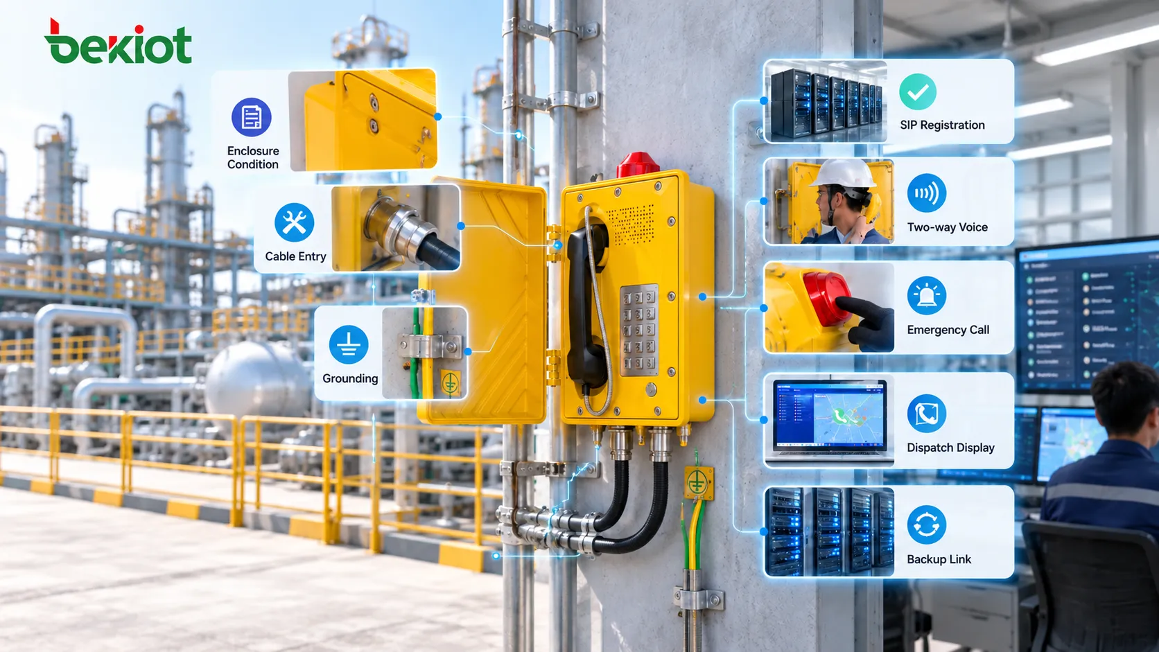
are the Cable Gland, Adapter and blanking components correctly installed;
is the cable free from abnormal tension, abrasion or compression;
do grounding, bonding and related connections follow the project requirements;
are product markings and warning labels still visible.
Communications testing should then confirm:
whether SIP registration or the analog line status is normal;
whether incoming calls, outgoing calls, hook switching and two-way voice operate correctly;
whether speech remains intelligible under the actual site noise conditions;
whether an emergency button or hotline call reaches the correct destination;
whether the dispatch console displays the correct terminal identity and location;
whether visual beacons, horns, recording or other configured integrations operate correctly;
whether backup servers, UPS systems or alternate call routes have been tested under actual failure conditions where they form part of the design.
A more complete post-installation test process is available in How Should an Explosion-Proof Telephone Be Tested After Installation?.
Which Installation Errors Are Most Important to Catch Before Handover?
Many explosion-proof telephone installation problems share the same pattern: short-term communications work normally while long-term risk has already been introduced. The most valuable pre-handover checks therefore focus not only on obvious faults, but also on installation details that can easily be hidden by the simple fact that the telephone still works.
| Field Condition | Common Assumption | What Actually Needs to Be Confirmed |
|---|---|---|
| Telephone is online and can make calls | Installation is complete | Area suitability, Cable Gland, blanking, grounding and initial inspection |
| Cable Gland is fully tightened | Cable entry must be correct | Gland type, thread, cable diameter and compatibility with the protection concept |
| Unused entry has been plugged | It is acceptable as long as water cannot enter | Whether the blanking element is suitable for the equipment and installation requirements |
| Equipment is mounted very securely | Mechanical installation is correct | Whether the enclosure, cable and bracket are under abnormal long-term stress |
| Equipment has a high IP rating | Water ingress is no longer a concern | Mounting orientation, cable routing, entry sealing, condensation and corrosion exposure |
| PoE is working | Emergency communications already have backup power | Whether the upstream switch, core network and SIP platform have appropriate backup capability |
| Voice is clear in the workshop or lab | Speech will be clear at the installation site | Two-way intelligibility under real noise conditions, PPE use and actual operating positions |
These checks are not intended to add unnecessary work for installers. Their purpose is to identify problems while the project is still in commissioning and handover. Discovering a Cable Gland, cable-stress, sealing or backup-communications problem after the equipment has already operated in a hazardous area for months or years is usually much more difficult and disruptive.
Installation Quality Determines Communication Quality
The real value of an explosion-proof telephone is usually demonstrated at the least convenient moment: a process abnormality, leak alarm, trapped worker, power failure, network switchover or urgent need to contact the control room. A good installation is therefore not one that simply looks neat on handover day. It is one that still has a clear equipment identity, reliable cable entries, stable mechanical mounting and a verifiable communications path years later.
From this perspective, the most important installation mistakes are often not the ones that prevent the telephone from powering up. Those failures are relatively easy to detect. The more difficult problems are the ones where the telephone still works and the project can still be handed over, but one of the controlled installation conditions has already been changed during construction.
Explosion-proof telephone projects therefore need to treat equipment selection, field installation, initial inspection and long-term maintenance as one continuous engineering chain. The equipment design provides the protection foundation. Field installation is responsible for preserving those conditions in the real environment, while inspection and maintenance confirm that the installed state has not gradually deteriorated through time, environmental exposure or human intervention.
For chemical, oil and gas, storage, energy and other hazardous-area communications projects, Becke Telcom provides explosion-proof SIP telephones, industrial communications terminals, IP PBX systems, SIP servers and command-and-dispatch platforms. Terminal and system configurations can be planned around hazardous-area conditions, communications architecture, site noise and emergency call workflows, followed by verification of the actual communications path after installation.
FAQ
If an Explosion-Proof Telephone Can Make Calls After Installation, Does That Mean the Installation Is Correct?
No. A successful call confirms that the communications function is currently available, but the installation still needs to be checked for hazardous-area suitability, equipment marking, cable entries, blanking elements, fasteners, grounding or equipotential bonding requirements and the results of the initial inspection.
Can a Standard Industrial Cable Gland Be Used on an Explosion-Proof Telephone?
Suitability cannot be determined only by whether the thread fits or the cable can be tightened. The Cable Gland needs to match the equipment's explosion-protection concept, cable-entry arrangement, thread, cable construction and project requirements. For protection concepts such as Ex “d”, the cable-entry device forms an important part of maintaining the original protection arrangement.
Can an Unused Entry on an Explosion-Proof Telephone Be Closed with an Ordinary Plug?
Unused entries need a blanking arrangement compatible with the equipment design and hazardous-area installation requirements. Ordinary plastic plugs, adhesive tape or temporary sealing materials should not be treated as an acceptable hazardous-area solution simply because they appear to prevent water ingress.
Does a PoE-Powered Explosion-Proof SIP Telephone Still Need Backup Power?
The answer depends on the entire communications path. PoE delivers power to the terminal through Ethernet, but the telephone can still lose service if the upstream PoE switch, core network or SIP server loses power. Where the telephone supports emergency calling, appropriate backup power and alternate communications paths should be considered as part of the system design.
What Records Should Be Kept After an Explosion-Proof Telephone Is Installed?
Useful records can include the equipment model and identification number, installation location, nameplate information, cable-entry configuration, line or network information, SIP number, emergency-call destination, field photographs, initial inspection results and actual call and integration test records. These records provide a reference for identifying changes during later maintenance.