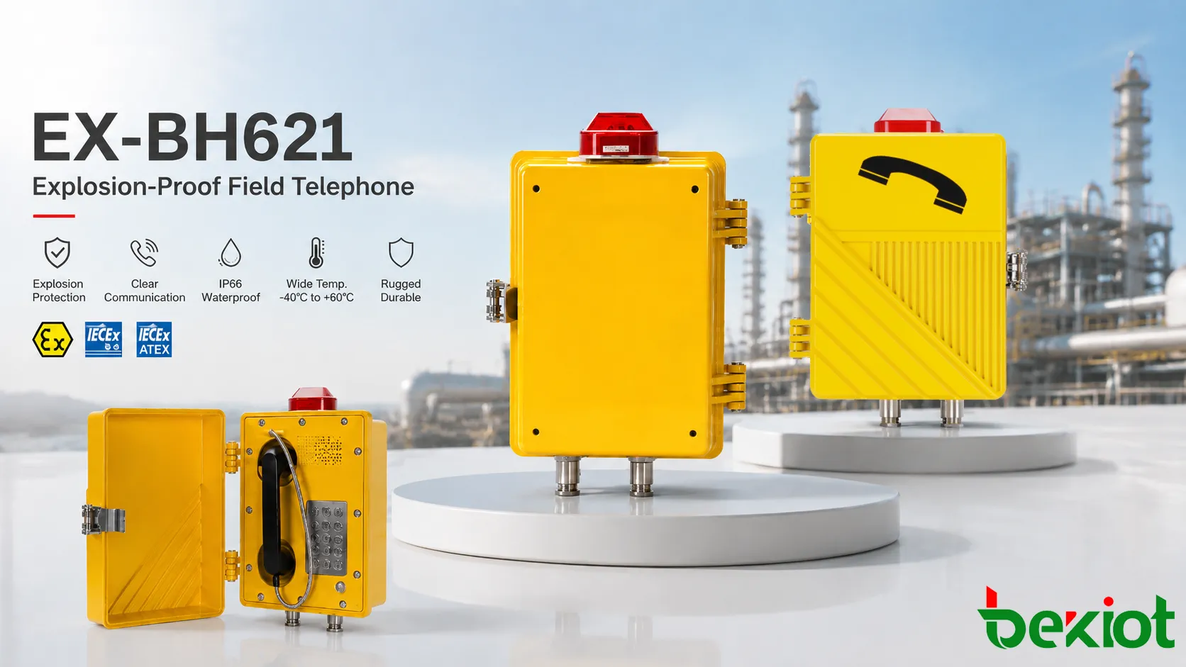
Explosion-proof telephones are used in places where ordinary communication devices may introduce unacceptable risk. Oil refineries, gas stations, petrochemical plants, chemical warehouses, offshore platforms, mines, tunnels, grain processing areas, paint facilities, power plants, and hazardous industrial zones may contain flammable gas, vapor, mist, combustible dust, or other explosive atmospheres. In these environments, communication equipment must be designed not only to make calls, but also to avoid becoming an ignition source.
The design principle of the explosion-proof structure is to control the relationship between electrical equipment and the surrounding hazardous atmosphere. A telephone may include switches, ringing circuits, microphones, speakers, terminals, electronic boards, handset wiring, and communication interfaces. Any spark, hot surface, arc, loose connection, or abnormal heat may become dangerous if it reaches a combustible atmosphere. A proper structure manages these risks through enclosure strength, flame containment, sealing, temperature control, cable protection, material selection, and installation discipline.
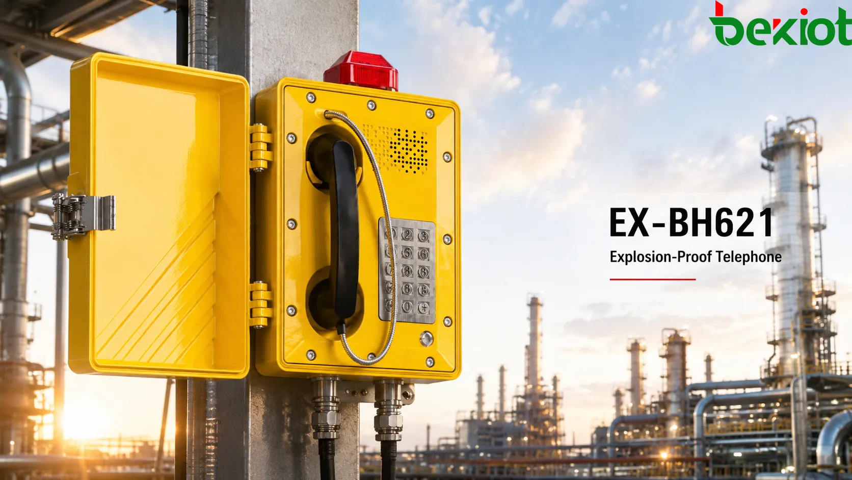
For industrial communication projects, this structure is not a decorative shell. It is part of the safety function. A well-designed explosion-proof telephone should keep its communication role while meeting the protection logic required by the site. Becke Telcom EX-BH621 is one example of a hazardous-area field telephone that can be considered when a project requires fixed voice communication in demanding industrial environments. The final selection should still match the site classification, installation method, and system integration requirements.
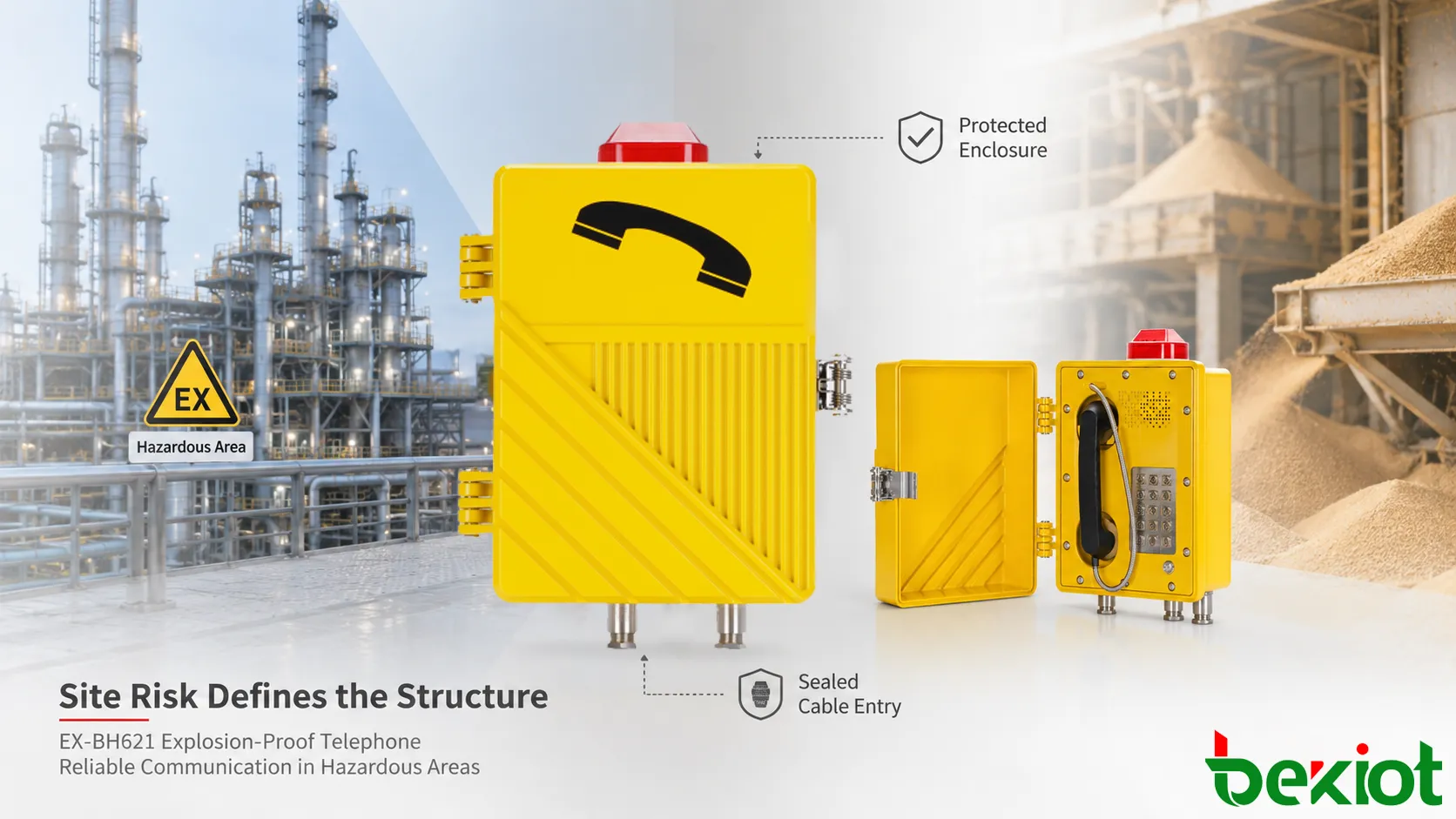
Site Risk Defines the Structure
The design of an explosion-proof telephone begins with the risk environment. The engineer must understand whether the location may contain flammable gas, vapor, dust, or fibers, how often the hazardous atmosphere may appear, and what substances may be present. The required structure for a telephone in a petrochemical process area may be different from one in a dusty grain facility, a tunnel, a battery material workshop, or an offshore loading area.
The basic risk model is often described through three elements: combustible substance, oxygen, and ignition source. A telephone cannot remove all combustible materials from an industrial site, and it cannot remove air from the environment. Its structural design therefore focuses on controlling ignition sources and preventing internal faults from igniting the surrounding atmosphere.
This principle affects every part of the product. The housing cannot crack easily. The cable entry cannot allow uncontrolled gas or dust passage. The button and hook switch cannot expose unsafe sparks. The speaker and microphone openings cannot become weak points. The internal circuit must be organized so that normal operation and expected faults do not create dangerous external effects.
Because the risk starts from the site, the explosion-proof structure should never be selected only by appearance. A strong-looking metal shell is not automatically suitable. The device must match the applicable hazardous area conditions and the protection concept required by the project.
Protection Methods Control Ignition
Ignition sources must be managed
The central design principle is ignition control. A telephone may appear to be a low-power device, but it still contains electrical contacts, signal circuits, ringing circuits, audio components, network modules, and terminals. During normal operation, these parts may switch, heat, vibrate, or carry current. During abnormal operation, they may short, loosen, overheat, or create sparks.
Explosion-proof structure reduces the chance that these internal behaviors can ignite the external atmosphere. Different protection methods can achieve this goal in different ways. Some designs contain an internal explosion and prevent flame propagation. Some limit electrical energy so ignition cannot occur under defined conditions. Some prevent hazardous material from entering critical parts. Some increase insulation, clearance, and mechanical security to reduce fault risk.
For telephones, the structural principle must also protect usability. The user still needs a handset, microphone, speaker, call button, keypad, label, hook switch, and cable connection. Each user-facing part must be designed so it can function without weakening the safety concept. A button that is convenient but poorly sealed may become a risk. A speaker opening that is loud but unprotected may damage the enclosure concept. A cable entry that is easy to wire but not suitable for hazardous areas may compromise the whole installation.
Containment depends on controlled joints
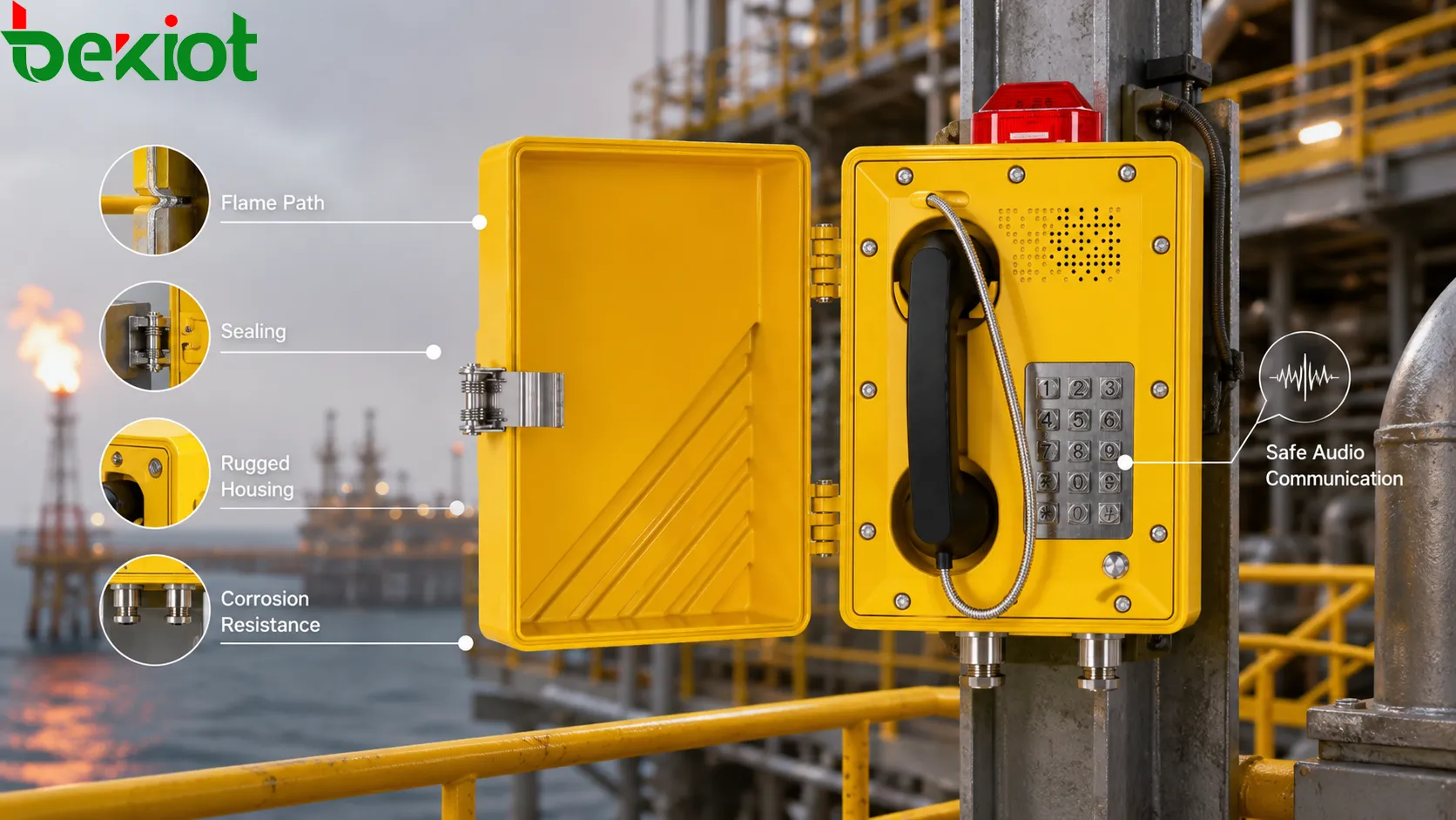
For many explosion-proof enclosures, one important principle is containment. If an internal ignition occurs within a protected enclosure, the structure must be able to withstand the pressure and prevent flame from escaping in a way that ignites the outside atmosphere. This is why enclosure strength, cover fit, joint design, screw engagement, wall thickness, and flame path geometry matter.
A flame path is not a random gap. It is a precisely controlled joint or passage designed to cool hot gases and prevent flame transmission to the external hazardous atmosphere. The surface quality, length, clearance, fastening, and protection from corrosion all affect whether the path remains effective. If the cover is loose, the joint is damaged, or the surface is painted, scratched, drilled, or contaminated incorrectly, the protective function may be weakened.
For a telephone, flame path design can be more complex than a simple sealed box because the equipment requires user interaction and communication openings. The handset cradle, cover joints, terminal chamber, cable entry area, speaker structure, and service cover may all require careful mechanical design. The product must allow maintenance access while preserving the controlled joint after reassembly.
Sealing keeps hazards away
Sealing is another structural principle. Hazardous gases, vapors, dust, moisture, salt mist, cleaning fluids, and corrosive air may enter equipment through weak points. Cable glands, cover joints, microphone openings, speaker paths, keypad areas, hook switches, drain features, and mounting interfaces must be considered carefully.
For gas environments, sealing may help prevent uncontrolled movement of flammable mixtures into sensitive areas, depending on the protection concept. For dust environments, sealing is especially important because combustible dust layers can accumulate, block heat dissipation, contaminate contacts, and create ignition hazards. Dust-tight or dust-protected structures must prevent dangerous dust ingress while still allowing the telephone to operate clearly.
Sealing also supports long-term reliability. Water ingress, oil mist, chemical vapor, or dust accumulation can damage circuits and reduce audio quality. A telephone that fails frequently may become a safety problem because emergency communication becomes unavailable. Structural sealing therefore protects both explosion-proof performance and communication service.
Materials and Audio Must Endure
Circuits must remain safe
Explosion-proof structure is not only mechanical. Internal electrical design is part of the safety principle. Circuits should be arranged to reduce sparking risk, limit abnormal heating, maintain proper insulation, and protect against short circuits or loose connections. The structure and circuit design should support each other.
Telephone circuits may include ringing voltage, audio amplification, SIP network electronics, analog line interfaces, relays, indicators, keypads, hook switches, and power inputs. Each part should be evaluated according to the protection concept. High-energy circuits may need stronger isolation or enclosure protection. Low-energy signal paths may still require careful separation and secure terminals.
Temperature control is especially important. An explosion-proof telephone should not allow external surfaces to exceed the permitted temperature class for the site. Internal components that generate heat must be placed and managed so heat does not become an ignition source. Enclosure material, surface area, thermal conduction, power consumption, and ambient temperature all affect this result.
Electrical protection may also include surge protection, grounding, bonding, fuse or current limiting design, and stable terminal connections. In outdoor industrial areas, lightning, switching surge, long cables, and grounding differences may damage communication equipment. A damaged circuit can create failure or risk, so electrical robustness supports the explosion-proof structure.
Materials must survive the site
Material selection is a core part of structural design. Hazardous industrial sites often involve corrosive gas, salt fog, oil, ultraviolet exposure, dust, vibration, mechanical impact, temperature variation, and cleaning chemicals. A telephone enclosure must maintain its protective shape, joint accuracy, sealing quality, and mounting stability over time.
Metals used in explosion-proof telephones should provide strength, dimensional stability, and resistance to site conditions. Surface treatment may help reduce corrosion, but it must not damage flame paths or critical joints. Non-metallic parts, if used, must be evaluated for mechanical strength, aging, static risk, heat resistance, and compatibility with the environment.
Handsets, cords, buttons, labels, gaskets, and cable entries also matter. These parts are touched frequently and exposed to the environment. If a handset cracks, a gasket hardens, a button becomes loose, or a cable gland corrodes, the overall product may lose reliability or safety integrity. A structure is only as strong as its vulnerable details.
For outdoor or marine environments, weather resistance becomes more important. Rain, humidity, salt air, and sunlight can gradually weaken unsuitable materials. For chemical plants, corrosion resistance may be the deciding factor. For mines or heavy industrial sites, impact resistance and dust protection may matter more. The design principle must follow the environment instead of assuming one material is suitable everywhere.
Sound must still pass clearly
A telephone is different from many other explosion-proof devices because it must handle sound. Users must speak into a microphone and hear the other side through a handset or speaker. The explosion-proof structure must therefore allow voice transmission without opening unsafe paths to the environment.
Microphone and speaker design require careful acoustic protection. If the structure blocks sound too much, speech becomes muffled and emergency communication may fail. If the sound path is too open, the enclosure concept may be weakened. A good design uses protected acoustic channels, suitable membranes, controlled openings, and rugged handset construction to balance audio clarity and safety.
Noise conditions also affect the structural requirement. Explosion-proof telephones are often installed near pumps, compressors, generators, conveyors, fans, vehicles, and alarms. The handset shape, microphone position, receiver output, and enclosure layout should help maintain speech intelligibility. In high-noise locations, a close-talk handset can improve signal-to-noise ratio.
Acoustic reliability must continue after long use. Dust, moisture, oil, corrosion, or impact can block microphone openings or speaker paths. Maintenance procedures should include checking audio clarity, not only visual inspection. A telephone that is structurally intact but acoustically unusable cannot support safety communication effectively.
Cable Entry Requires Discipline
Cable entry is one of the most important parts of explosion-proof telephone installation. Communication cables, power cables, network cables, grounding conductors, and external speaker or relay lines may all pass through the enclosure boundary. If this boundary is poorly designed or installed, the protective structure may be compromised.
Cable glands, conduit entries, sealing fittings, terminal chambers, strain relief, and grounding points should match the hazardous-area requirements. A cable entry should prevent mechanical pulling from damaging internal terminals. It should also help maintain sealing, flame containment, dust protection, and environmental resistance.
The correct cable type is also important. Outdoor, chemical, marine, underground, or high-temperature locations may require special cable jackets and protection. If the cable degrades, cracks, or allows moisture movement, the telephone may fail even if the enclosure is well designed. Cable planning should therefore be treated as part of the explosion-proof structure, not as a separate installation detail.
Field modification is a common risk. Drilling extra holes, replacing certified glands with ordinary fittings, using loose plugs, or leaving unused entries improperly sealed can weaken safety. The structure should be installed according to approved methods, and any change should be reviewed by qualified personnel.
This part is also closely related to service reliability. A loose cable gland may not only weaken protection; it can also cause intermittent communication, water ingress, line noise, corrosion, or terminal damage. For analog telephones, cable condition can affect ringing, voice level, and line stability. For SIP or IP-based telephones, cable condition can affect network registration, PoE power, packet transmission, and device online status.
In hazardous-area projects, cable entry should be documented clearly. The installation record should identify the cable type, gland type, sealing method, grounding point, unused entry treatment, and inspection result. This makes future maintenance safer and prevents unauthorized changes from being overlooked.
Installation Completes the System
Mounting affects safety and use
An explosion-proof telephone is not complete until it is installed correctly. Even a well-designed product can lose its protective value if the cover is not tightened, the gasket is damaged, the cable gland is wrong, the grounding is missing, or the enclosure is mounted in a location beyond its environmental rating. Installation is part of the safety chain.
Mounting should support both safety and usability. The telephone should be reachable during an emergency, visible enough for workers to find, and protected from direct mechanical damage where possible. It should not be installed where water collects, where cables are pulled, where chemical spray is constant, or where users cannot safely stand and speak.
Grounding and bonding should follow the project design. Poor grounding can increase surge risk, electrical noise, and safety concerns. In communication systems, grounding also affects audio stability and equipment protection. The mechanical structure, cable shields, surge protectors, and platform grounding plan should be coordinated.
Integration keeps calls useful
Explosion-proof telephones are often connected to larger communication systems. They may link with analog telephone exchanges, SIP platforms, IP PBX systems, dispatch consoles, public address systems, emergency call systems, alarm platforms, or recording systems. The structure protects the field endpoint, but system integration protects communication continuity.
For SIP or IP-based devices, network stability, PoE or power supply design, registration status, codec settings, and platform routing must be checked. For analog devices, line voltage, loop current, ringing, cable distance, and surge protection are important. The telephone must remain reachable when workers need it.
In emergency environments, the telephone may also trigger or support alarm workflows. A call from a hazardous area may need to display location, record audio, alert the control room, or link with video and dispatch systems. The structural design allows the device to exist safely in the field; the system design ensures that its call creates a useful response.
Becke Telcom EX-BH621 can be positioned as a field communication point in such integration scenarios, especially where hazardous-area communication, rugged enclosure design, and operational voice access must work together. The project should still evaluate whether the selected version, wiring method, and platform interface match the actual site.
Testing proves readiness
Testing and inspection are necessary because explosion-proof performance depends on details that may not be visible from a distance. The enclosure may look strong, but the cover joint, cable gland, gasket, screw torque, grounding point, and internal wiring must also be correct. Field inspection helps confirm that the structural principle remains intact after installation.
Functional testing should include call setup, ringing, audio clarity, handset operation, button response, line stability, speaker output, and communication with the control room. Safety-related inspection should include enclosure condition, entry fittings, seals, fasteners, corrosion, surface damage, and label readability. If the equipment is networked, registration and monitoring should also be checked.
Periodic inspection is important because hazardous sites change over time. Vibration may loosen fittings. Corrosion may damage surfaces. Dust may collect around openings. Maintenance work may accidentally disturb cable entries. Outdoor exposure may age gaskets or labels. A device that was safe at commissioning may need attention after years of service.
Testing should also include emergency workflow. If the telephone is part of a safety communication plan, operators should confirm who answers the call, whether the location is shown correctly, whether audio is recorded if required, and whether response procedures are clear. Structural safety and communication readiness should be reviewed together.
Wrong changes weaken protection
One common mistake is assuming that any heavy metal telephone is explosion-proof. True explosion-proof design depends on approved protection principles, controlled joints, suitable materials, correct cable entries, electrical safety, and installation compliance. A rugged industrial phone is not automatically suitable for hazardous areas.
Another mistake is modifying the enclosure in the field. Drilling additional holes, changing glands, replacing fasteners, painting over flame paths, using incorrect plugs, or repairing damaged parts without proper review can compromise protection. Field convenience should never override safety design.
Poor maintenance is also a risk. Corrosion, missing screws, cracked handsets, damaged cords, loose covers, blocked acoustic openings, and water ingress may gradually weaken the telephone. Regular inspection should be part of the site’s safety management process.
A fourth mistake is ignoring classification. A telephone suitable for one hazardous area may not be suitable for another. Gas group, dust condition, temperature class, ambient temperature, corrosion level, and installation method can all affect selection. Equipment should be matched to the specific risk environment.
Selection should be systematic
Selecting an explosion-proof telephone should follow a systematic process. First, identify the hazardous area conditions, including gas or dust type, zone or division classification, ambient temperature, corrosion level, and installation environment. Second, define the communication requirement: analog or SIP, hotline or dial keypad, handset or hands-free, ringing, speaker output, recording, dispatch connection, and alarm linkage.
Third, check structural suitability. The enclosure, cable entries, mounting method, material, protection level, acoustic design, and service access should match the location. Fourth, evaluate power and communication cabling. Long cable runs, outdoor routes, lightning exposure, network switches, and grounding plans should be included in the design.
Fifth, plan maintenance before installation. Technicians should know how to inspect the enclosure, clean the device, test audio, verify cable glands, check grounding, and confirm platform connectivity. Good selection includes lifecycle management, not only product purchase.
For projects considering Becke Telcom EX-BH621, the same systematic approach should apply. The model can be evaluated as part of a hazardous-area communication solution, but final configuration should reflect the actual site conditions, safety requirements, and communication architecture.
FAQ
What does explosion-proof structure mean for a telephone?
It means the telephone is structurally designed to control ignition risks in hazardous environments through enclosure protection, flame path design, sealed cable entries, safe circuits, suitable materials, and correct installation methods.
Is a waterproof telephone the same as an explosion-proof telephone?
No. Waterproofing mainly protects against water ingress. Explosion-proof design addresses ignition risk in hazardous atmospheres. A device may be waterproof but not suitable for explosive gas or dust environments.
Why are cable glands important?
Cable glands protect the enclosure boundary where cables enter the telephone. Incorrect glands, loose fittings, or unused entries can compromise sealing, mechanical protection, and explosion-proof performance.
Can users modify the enclosure on site?
Field modification should be avoided unless reviewed and approved by qualified personnel. Drilling, replacing fittings, changing fasteners, or damaging flame paths can weaken the protective structure.
What should be checked during maintenance?
Maintenance should check enclosure condition, screws, cover joints, cable entries, grounding, corrosion, handset, microphone, speaker, labels, communication function, and system connectivity.
Final Notes for Projects
The design principle of an explosion-proof telephone structure is to control ignition risk while preserving reliable communication. The structure must protect the internal electrical parts, manage flame or energy hazards, resist harsh environments, maintain sealed and controlled cable entries, support clear audio, and remain serviceable through proper installation and inspection.
Good explosion-proof design is not defined by one feature. It is the result of many coordinated details: enclosure strength, flame path accuracy, material durability, electrical safety, temperature control, acoustic protection, cable entry design, grounding, mounting, maintenance, and system integration. If one detail is ignored, the overall safety and reliability of the telephone may be reduced.
For hazardous industrial sites that require fixed field communication, Becke Telcom offers the EX-BH621 explosion-proof telephone as one option for environments where rugged structure, safety-oriented design, and dependable voice access are important. The most suitable solution should be selected after reviewing the site classification, installation conditions, communication platform, cable design, and long-term maintenance plan.