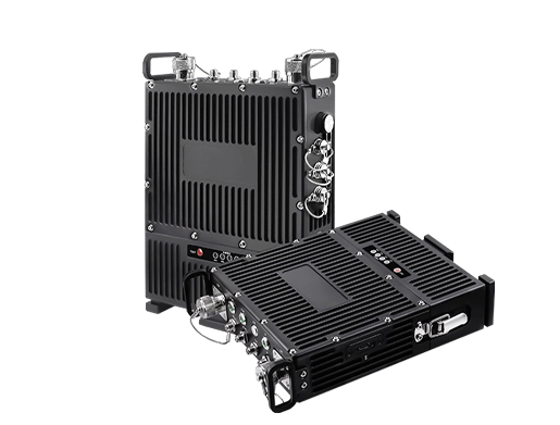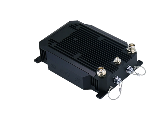
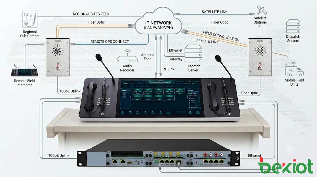
An IP-based radio dispatch system connects professional radio networks with RoIP gateways, dispatch consoles, recording services, SIP platforms, and remote control centers. Operators can monitor radio channels, initiate push-to-talk calls, coordinate field teams, handle emergency alarms, and manage communication across multiple sites from a unified interface.
The main engineering challenge is not simply converting radio audio into IP packets. A dependable system must also carry PTT control, channel status, emergency events, operator permissions, recording metadata, equipment alarms, and management information. A fault anywhere in this chain can result in delayed transmission, one-way audio, clipped speech, incorrect channel routing, or failed emergency calls.
1. What Is an IP-Based Radio Dispatch System?
An IP-based radio dispatch system brings conventional or digital radio channels into a networked communication environment. Instead of placing a separate physical radio beside every operator, base stations and repeaters can be connected through RoIP gateways and managed from centralized or distributed dispatch consoles.
The system may connect analog FM, DMR, TETRA, P25, PDT, NXDN, portable radios, vehicle radios, base stations, repeaters, and other professional radio equipment. The radio network continues to provide field coverage, while the IP layer extends channel control, recording, monitoring, and multi-site communication.
This architecture is suitable for organizations operating several radio channels, facilities, control rooms, or geographic regions. Authorized operators can access remote radio resources through the network without relocating the original radio equipment or building a separate control system at every site.
From Local Radio Consoles to Networked Dispatch
Traditional dispatch systems were often built around fixed wiring between a local radio base station and a nearby operator console. This arrangement could support one facility, but adding another site usually required additional radio equipment, dedicated cabling, and a separate operator position.
With IP-based control, radio audio and signaling can travel through a LAN, private WAN, fiber network, microwave link, VPN, cellular backhaul, or satellite connection. A primary command center can supervise remote radio sites, while an authorized backup center can take over selected channels when the main control room becomes unavailable.
The radio system therefore becomes part of a wider operational communication environment that may also include SIP telephony, GIS, video surveillance, alarm systems, broadband push-to-talk, recording platforms, and incident management software.
2. System Architecture and Signal Flow
A practical radio dispatch system can be divided into four functional layers. Understanding these layers helps engineers design the network and identify whether a fault originates in the RF system, radio interface, IP network, dispatch server, or operator console.
Radio Access Layer
The radio access layer includes portable radios, mobile radios, base stations, repeaters, antennas, RF channels, feeders, and related infrastructure. It determines field coverage, speech quality, channel capacity, interference performance, and how field users communicate through push-to-talk.
IP integration does not correct poor RF design. Coverage gaps, unsuitable antenna placement, excessive feeder loss, interference, or overloaded radio channels will continue to affect communication even when the dispatch platform and data network are working normally.
Gateway and Interface Layer
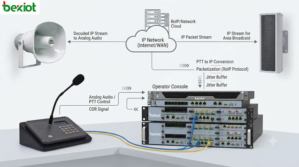
The gateway layer connects radio equipment to the IP network. Depending on the available interface, a gateway may process analog audio input and output, PTT control, COR or COS detection, GPIO signals, serial data, channel status, or proprietary control information.
On the network side, these signals are converted into media streams and control messages that can be processed by the dispatch platform. Gateway functions may also include codec selection, gain adjustment, jitter buffering, silence detection, remote configuration, and equipment status reporting.
Core Control Layer
The core layer contains the dispatch server, media routing services, user accounts, permissions, channel configurations, recording services, event logs, databases, and integration interfaces. It determines which operator may access a channel, how an emergency event is handled, where communication is recorded, and which radio groups may be connected.
Operator Application Layer
The operator layer includes hardware dispatch consoles, touch-screen terminals, desktop applications, web clients, and mobile dispatch interfaces. Operators use these tools to monitor channels, transmit audio, create temporary patches, acknowledge alarms, review recordings, and supervise equipment status.
Channel names and group layouts should reflect actual operations. Labels such as “Plant Emergency,” “North Station Security,” or “Maintenance Team 1” are easier to identify during an incident than internal radio IDs or gateway port numbers.
How Radio Voice and PTT Travel
When a field user presses PTT, the portable or mobile radio transmits over the RF channel. A repeater or base station receives the transmission and provides audio and receive status to the RoIP gateway. The gateway converts the audio into an IP media stream and forwards it to the dispatch server or authorized operator consoles.
When the dispatcher responds, the console sends operator audio through the IP network to the gateway. The gateway activates the radio transmitter, waits for the configured PTT lead time, and then sends audio into the radio channel.
This timing must be adjusted for the connected radio equipment. If audio is released before the transmitter is ready, the first syllable may be lost. If PTT remains active for too long after speech ends, the channel may carry unnecessary tail noise and remain occupied longer than required.
3. Core Radio Dispatch Functions
Centralized Channel Control
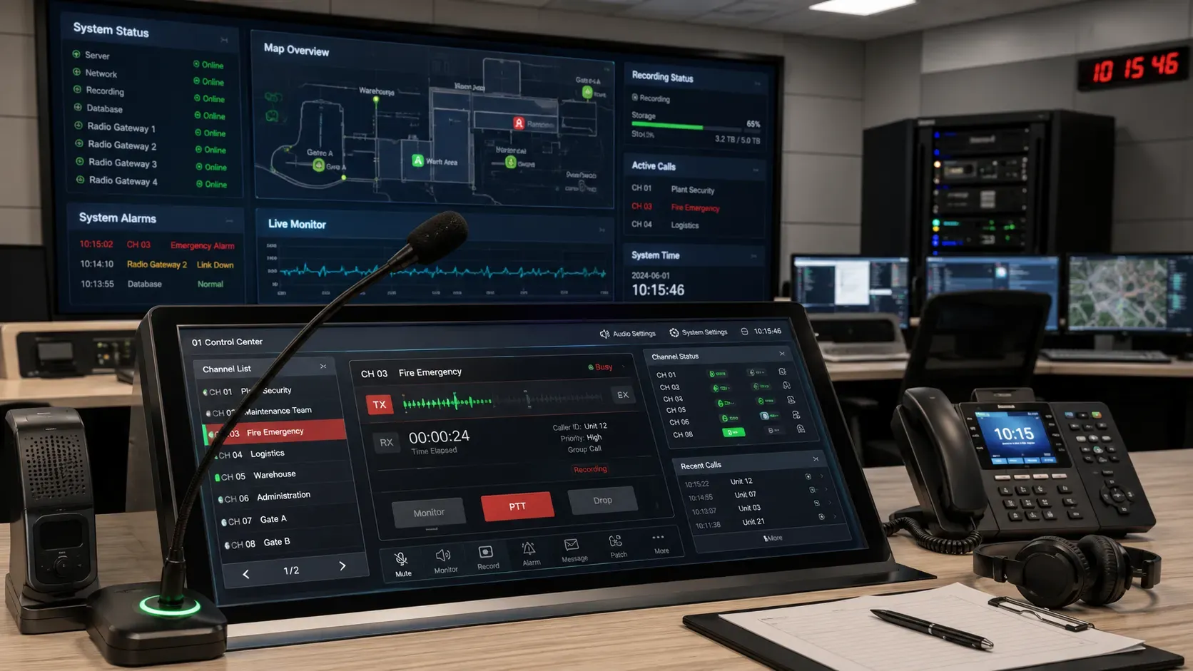
A radio dispatch console can present multiple channels, departments, sites, or talk groups on one interface. Operators can monitor several channels while transmitting only on the selected group for which they have permission.
This removes the need to place several physical radios at every operator position and allows remote radio sites to be managed from one control room.
Group Call and Channel Monitoring
Professional radio communication is normally organized around channels, talk groups, regions, fleets, or operational departments. A dispatcher may monitor several groups simultaneously while communicating with one selected team.
Receive indicators, channel-busy status, calling identity, transmission direction, and priority status help the operator understand current activity and avoid interrupting an active conversation.
Emergency Alarm Handling
If supported by the radio network, an emergency signal can identify the caller, highlight the relevant group, play an alarm tone, open an incident record, start recording, and notify a supervisor or another control position.
The alarm should remain visible until an authorized operator acknowledges it. Muting the audible tone should not automatically clear the event or remove its record from the dispatch workflow.
Cross-Channel Patching
Channel patching temporarily connects two or more radio groups or communication systems. It is useful when security, maintenance, fire response, management, and external teams normally use different radio resources but must coordinate during the same event.
The interface should clearly show which channels are patched, which operator created the connection, and when it was released. Permanent or uncontrolled patches can create congestion, feedback, and permission conflicts.
Recording and Event Playback
Radio recording supports incident review, training, compliance, dispute resolution, and operational analysis. A useful record includes more than audio. It should also retain timestamps, channel names, operator identities, transmission direction, emergency tags, and related event information.
Playback should support searches by time, channel, operator, event type, and incident reference. Without structured metadata, investigating a large recording archive becomes slow and unreliable.
| Function | Typical Capability | Operational Purpose |
|---|---|---|
| Voice dispatch | PTT, channel selection, group call | Coordinates field teams and control rooms |
| Emergency handling | Priority alarm, acknowledgement, escalation | Identifies and processes urgent events |
| Interoperability | Channel patching, SIP linkage, remote gateways | Connects different systems and locations |
| Recording | Audio, timestamps, IDs, event metadata | Supports investigation and accountability |
| System supervision | Gateway status, link alarms, service monitoring | Provides early warning of communication faults |
4. RoIP Gateway, Network, Security, and Integration
Matching the Gateway to the Radio Interface
The RoIP gateway must match both the connected radio equipment and the dispatch platform. Radio-side interfaces may include balanced or unbalanced audio, microphone-level or line-level signals, PTT input and output, squelch detection, COR/COS status, serial data, and external control contacts.
Different radios and repeaters may use different connector pinouts, voltage levels, grounding methods, and control behavior. Protocol compatibility alone does not guarantee that the gateway will work correctly without the proper cable and parameter adjustment.
On the IP side, the gateway may use RTP, SIP, multicast, unicast, or a platform-specific control protocol. A multi-channel RoIP gateway is suitable when several radio channels or remote radio sites need to be connected to one dispatch environment.
Audio and PTT Adjustment
Audio gain should be checked at the radio output, gateway input, gateway output, and radio transmit input. Increasing one setting to compensate for an incorrectly configured interface may introduce distortion, noise, or echo elsewhere in the path.
PTT lead time, audio delay, release time, squelch behavior, and silence detection should be tested with the actual base station or repeater. Default values cannot be assumed to suit every radio model.
Latency, Jitter, and Quality of Service
A clean test on an unloaded local network proves very little. PTT response, speech quality, jitter, and packet loss should also be tested while the WAN is carrying normal operational traffic.
Excessive delay causes dispatchers and field users to speak over one another. Packet loss and unstable jitter may produce broken audio or missing words. Cellular, satellite, VPN, and long-distance WAN links require additional testing under changing network conditions.
Dispatch media and signaling should receive appropriate network priority. QoS markings need to be recognized across switches, routers, firewalls, VPN equipment, and service-provider links. Marking traffic at the gateway alone is ineffective if intermediate equipment removes or ignores the priority.
Security and Operator Permissions
Radio dispatch systems may control safety-related or operational channels. User authentication, role-based permissions, network segmentation, secure management access, event logging, and regular account review should be included in the design.
Not every operator should be allowed to transmit on every radio group. Emergency channels, external-agency patches, management groups, and restricted operational channels may require supervisor authorization.
Telephone, GIS, Video, and Alarm Integration
Radio channels can be connected to SIP phones, PBX systems, emergency conference groups, or command-center communication platforms. The access policy should define who may enter a radio group, whether DTMF control is permitted, whether bridged calls are recorded, and how long an unattended connection may remain active.
If radios or vehicles provide location data, the dispatch platform can display field units on a GIS map. Operators can identify nearby resources, review patrol routes, and understand which teams are closest to an incident.
Emergency buttons, access control, fire systems, video analytics, industrial sensors, and incident platforms may also trigger radio workflows. An alarm can open the correct radio group, display its location, present a nearby camera, notify the duty operator, and attach recordings to an incident record.
Redundancy and Time Synchronization
Critical systems may require redundant dispatch servers, backup gateways, dual switches, separate WAN routes, standby consoles, and protected power supplies. These components should not share the same switch, power circuit, cable tray, or building entrance if they are expected to protect against a common failure.
Servers, gateways, operator consoles, and recording platforms should use a consistent time source. Accurate timestamps are necessary to reconstruct the order of transmissions, alarms, recordings, and operator actions.
5. Industry Applications
| Industry | Typical Users and Locations | Main Dispatch Requirements |
|---|---|---|
| Public safety | Police, fire, medical teams, command vehicles, temporary incident posts | Priority PTT, emergency alarms, cross-agency patching, resilient control positions |
| Rail and transportation | Stations, depots, vehicles, maintenance teams, operations centers | Multi-site control, remote dispatch, group coordination, communication records |
| Airports and ports | Ground operations, security, maintenance, logistics, emergency response | Department groups, temporary patches, wide-area coverage, incident coordination |
| Utilities | Substations, pipelines, field crews, repair teams, remote facilities | Distributed-site communication, backup links, alarms, maintenance records |
| Industrial and mining | Production areas, warehouses, underground zones, control rooms, safety teams | Reliable PTT, rugged radio access, emergency groups, redundant infrastructure |
| Campuses and private facilities | Security, parking, maintenance, cleaning, event and emergency teams | Simple operation, building-to-building networking, recording and temporary groups |
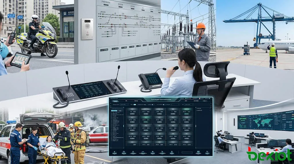
The operational environment changes from one industry to another, but the core requirement remains consistent: field users need immediate access to the correct communication group, while the control center requires visibility, permissions, recording, and a clear incident workflow.
6. Deployment, Reliability, and Troubleshooting
Define the Workflow Before Selecting Equipment
Before selecting gateways and consoles, define the number of radio channels, sites, operators, control rooms, user groups, emergency procedures, recording policies, and external integrations.
The channel plan should reflect real responsibilities. It must be clear which operator monitors each group, who may transmit, how an emergency event is escalated, and how communication continues if the main control center is unavailable.
Verify Radio Interface Compatibility
Not every radio or repeater provides the same audio, PTT, status, or data interface. Wiring diagrams, connector pinouts, signal levels, grounding, and control behavior should be confirmed before installation.
A gateway supporting the required IP protocol may still require a dedicated interface cable and model-specific parameter adjustment.
Test the Complete Communication Chain
Acceptance testing should cover more than a successful test call. Engineers should verify:
Field-radio audio received at the dispatch console;
Dispatch-console audio transmitted through the radio;
PTT response and first-syllable integrity;
Channel-busy and receive-status indicators;
Emergency alarm acknowledgement and escalation;
Recording, timestamps, and metadata retrieval;
Channel patch creation and release;
Gateway, server, network, and power failover;
Operation during network congestion;
Local radio communication after IP backhaul failure.
Common Faults and Diagnostic Order
Common faults include one-way audio, delayed PTT, clipped speech, low transmission volume, incorrect channel routing, missing recordings, unstable gateway registration, packet loss, firewall blocking, and IP-address conflicts.
Troubleshooting should separate the RF side from the IP side:
Confirm that the radio channel works locally without the IP dispatch platform.
Check whether the gateway receives radio audio and COR/COS status.
Verify that the gateway activates PTT and sends clean audio to the radio.
Confirm that media and control packets reach the dispatch server.
Check operator permissions, channel routing, and console audio devices.
Verify recording services, storage capacity, and time synchronization.
This sequence prevents repeated network changes when the actual cause is a radio cable, signal level, grounding issue, or PTT interface.
Common Design Mistakes
Treating radio integration as an audio-only connection;
Using unclear or inconsistent channel names;
Giving too many operators access to critical groups;
Sending dispatch traffic over an unprotected WAN without QoS or backup;
Installing redundant servers while retaining a single switch or power circuit;
Failing to test alarms, patches, recordings, and fallback procedures before operation.
Final acceptance should include realistic communication drills, failover tests, and incident workflows rather than configuration checks alone.
7. Future Direction and FAQ
Professional radio dispatch is moving toward converged communication. Radio channels increasingly operate alongside broadband PTT, LTE or 5G services, SIP telephony, satellite links, video dispatch, GIS, IoT alarms, and software-based command platforms.
This does not mean conventional professional radio will disappear. Dedicated radio continues to provide immediate group calling, simple field operation, independent RF coverage, and predictable behavior during busy or high-risk events.
The practical direction is to retain professional radio for dependable field access while using IP architecture to extend control, recording, interoperability, and multi-site coordination.
Can an Existing Analog Radio System Be Connected?
In many cases, yes. The radio or repeater must provide suitable audio, PTT, and preferably channel-status interfaces. A RoIP gateway converts these signals into IP media and control information.
Does Every Site Need a Local Dispatcher?
No. Remote radio sites can be managed from a central control room through the IP network. A local console may still be retained at an important facility as a backup or operational control point.
What Happens if the IP Backhaul Fails?
Local radio users may continue communicating through the local RF system if the repeater or base station remains operational. Remote dispatch access will normally be interrupted unless a backup link, secondary control center, or local fallback procedure is available.
Is GPS Required?
No. PTT dispatch, group communication, channel monitoring, and recording can operate without GPS. Position data is an additional capability used for map display, field-unit selection, and resource tracking.
How Should Channel and Group Names Be Planned?
Names should reflect actual departments, locations, functions, or emergency roles. Operators must be able to identify the correct group immediately without translating technical radio codes during an incident.
Which Dispatch Console Is Suitable?
The choice depends on the number of channels, operator workflow, display size, paging requirements, and external integrations. A project may use a dedicated IP dispatch console, an IP paging and dispatch console, or a software-based operator interface.
An IP-based radio dispatch system creates value when radio channels, operators, remote sites, and incident procedures are managed as one communication environment. The final result depends on correct RF coverage, compatible gateway interfaces, controlled permissions, resilient networking, and operating procedures that remain clear under pressure.