High-voltage load break switches are switching devices used in medium- and high-voltage power distribution systems to make, carry, and interrupt load current under specified service conditions. They are commonly applied in ring main units, distribution substations, overhead lines, industrial power systems, transformer feeders, cable networks, renewable energy substations, and utility distribution automation projects.
A load break switch is not the same as a circuit breaker. Its primary role is load switching and isolation, while a circuit breaker is designed to interrupt fault currents. In many distribution systems, load break switches are used together with fuses, protection relays, disconnectors, earthing switches, interlocks, and control devices to support safe operation and reliable power distribution.
A high-voltage load break switch provides controlled switching of normal load current, but it must be selected, operated, and maintained according to its rated capacity and the safety rules of the power system.
Basic Meaning of a High-Voltage Load Break Switch
A high-voltage load break switch is a mechanical switching device designed to open and close electrical circuits while the circuit is carrying load current. It allows operators or control systems to energize, de-energize, sectionalize, or transfer parts of a power distribution network under normal operating conditions.
In practical power systems, the term “high-voltage” may be used differently by region and industry. Many load break switches in distribution applications are found in voltage classes above 1kV, especially in medium-voltage networks such as 6kV, 10kV, 11kV, 12kV, 24kV, 33kV, and 35kV systems. The exact voltage class, insulation level, current rating, and switching duty must match the project design and applicable standards.
Load Switching Function
The main function of the device is to switch load current. This means it can interrupt the current flowing during normal service, such as transformer load current, feeder load current, cable charging current, or distribution line load current within its rated capability.
This function is important because opening a high-voltage circuit under load creates an arc. A load break switch includes an arc-control structure so that the arc can be managed and extinguished safely within the rated switching conditions.
Isolation and Sectionalizing
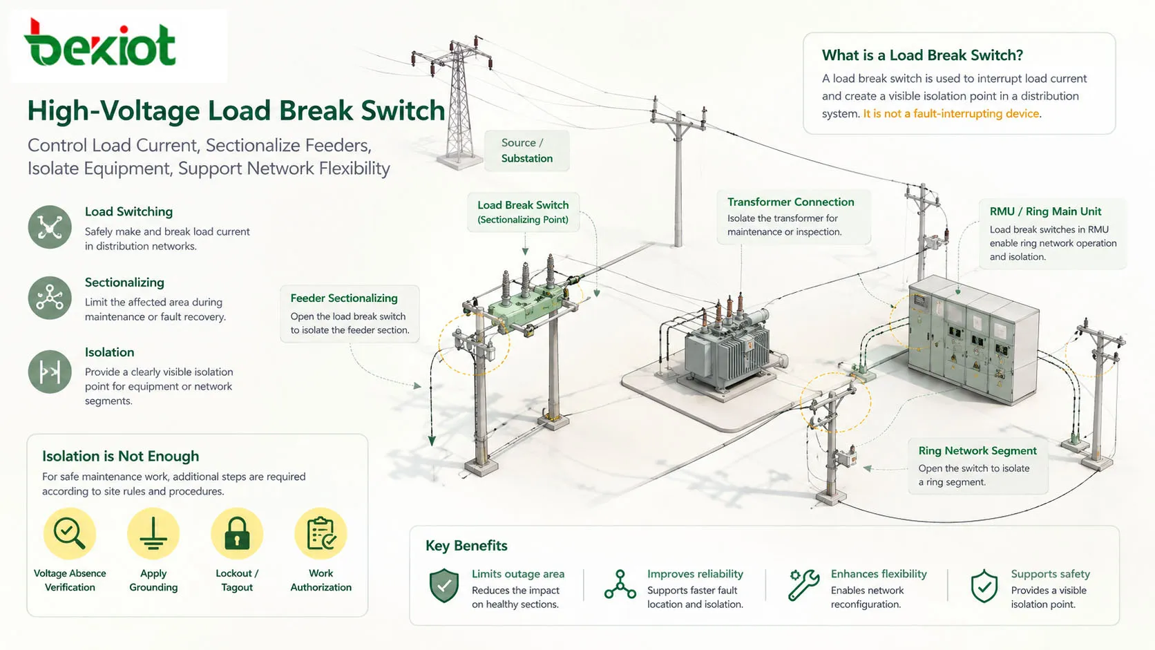
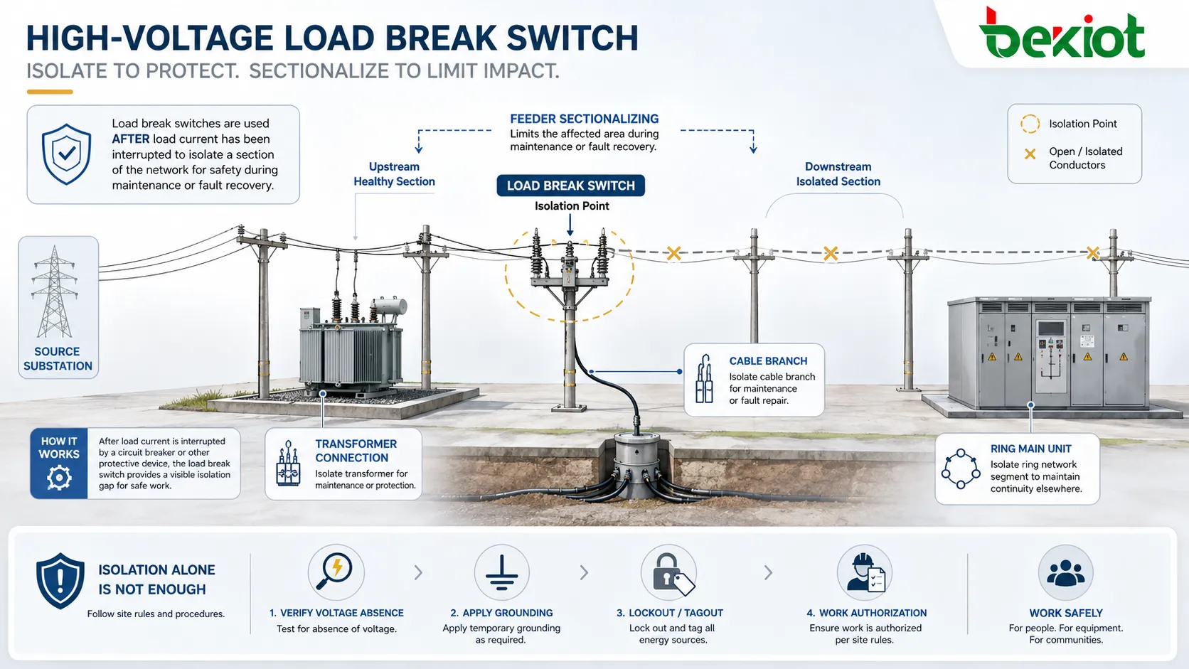
Many load break switches are used to isolate a feeder section, transformer, cable branch, or ring network segment after load current has been interrupted. In distribution networks, sectionalizing helps limit the affected area during maintenance or fault recovery.
Isolation must be clearly visible or reliably indicated according to the switchgear design. For maintenance work, isolation alone is not enough; voltage absence verification, grounding, lockout procedures, and work authorization are also required according to site rules.
Operating Principle
The operating principle of a load break switch is based on fast contact movement and arc interruption. When the switch opens under load, the moving and fixed contacts separate. An electrical arc forms between the contacts because current continues to flow through ionized gas or arc medium for a short time.
The switch must then stretch, cool, split, blow, or extinguish the arc so that the current stops safely. The arc interruption method depends on the switch design. Common designs may use air, gas, vacuum, oil in older equipment, or other arc-control structures.
Contact Opening and Arc Formation
When the switch is closed, current flows through the main conductive path. During opening, the contacts separate quickly. Because the circuit has inductance and electrical energy, the current does not stop instantly. This produces an arc.
If the arc is not controlled, it can damage contacts, insulation, and nearby equipment. It can also create serious safety risks. Therefore, the load break switch must have a rated interruption capability suitable for the expected load current and operating duty.
Arc Extinction
Arc extinction is the process of stopping the arc and restoring insulation between the open contacts. Different switch designs use different methods. Air load break switches may use arc chutes, arc horns, or arc-extinguishing chambers. Gas-insulated designs may use gas flow and insulation properties. Vacuum interrupters extinguish the arc inside a sealed vacuum chamber.
The purpose is the same: interrupt load current without allowing the arc to continue or restrike beyond safe limits. The switch must be tested and rated for the intended voltage, current, frequency, and switching duty.
Stored Energy Mechanism
Many load break switches use a spring or stored-energy mechanism. The operator charges the mechanism manually or electrically, and the mechanism releases energy to move the contacts quickly.
Fast and consistent contact movement is important because slow manual movement can increase arcing time and reduce switching reliability. Stored-energy mechanisms help make switching speed less dependent on the operator’s hand movement.
Open, Closed, and Earthed Positions
Some switchgear designs provide multiple positions such as closed, open, and earthed. The closed position connects the circuit. The open position separates the circuit. The earthed position connects the isolated circuit side to ground through an earthing switch.
Position indication must be clear and reliable. Interlocks are often used to prevent unsafe operations, such as closing an earthing switch onto an energized circuit or closing the load break switch while the earthing switch is engaged.
Main Structural Components
A high-voltage load break switch is built from electrical, mechanical, insulation, and control components. The exact structure depends on whether the switch is indoor, outdoor, air-insulated, gas-insulated, pole-mounted, metal-enclosed, or integrated into a ring main unit.
Main Contacts
Main contacts carry the normal operating current when the switch is closed. They must have low resistance, adequate thermal capacity, and sufficient mechanical strength.
Contact wear, oxidation, poor alignment, or overheating can reduce reliability. Regular inspection and maintenance should follow the manufacturer’s instructions and site maintenance policy.
Arc Interruption System
The arc interruption system controls the arc during opening. It may include arc runners, arc chutes, interrupter chambers, gas flow paths, vacuum bottles, or arc-resistant structures.
This part is critical to safe load switching. If the arc interruption system is damaged or contaminated, the switch may fail to interrupt load current safely.
Insulation System
The insulation system separates live parts from grounded metal parts, phase-to-phase conductors, and accessible surfaces. Insulation may include air clearance, solid insulation, gas insulation, porcelain, epoxy resin, or composite materials.
Insulation performance can be affected by moisture, dust, pollution, aging, mechanical damage, partial discharge, and incorrect installation. Environmental conditions should be considered during selection and maintenance.
Operating Mechanism
The operating mechanism transfers manual or motorized action into contact movement. It may include handles, shafts, springs, latches, linkages, motors, auxiliary switches, and mechanical position indicators.
The mechanism should operate smoothly and consistently. Any stiffness, abnormal sound, incomplete travel, or position mismatch should be investigated by qualified personnel before continued operation.
Interlocks and Indication
Interlocks help prevent unsafe switching sequences. Position indicators show whether the switch is open, closed, or earthed. Auxiliary contacts may send status signals to monitoring systems, SCADA platforms, or remote control units.
Reliable indication is essential because operators must know the actual switch state before performing switching, testing, grounding, or maintenance activities.
Types of Load Break Switches
Load break switches can be classified by insulation medium, installation environment, operating method, and application. Each type has different advantages and limitations.
Air-Insulated Load Break Switch
Air-insulated load break switches use air as the primary insulation medium. They are often simple, visible, and easier to inspect. They may be used in indoor switchgear, outdoor pole-mounted systems, or distribution equipment depending on design.
Air-insulated designs require adequate clearance and may be more affected by pollution, humidity, salt, dust, and environmental exposure. Maintenance and installation conditions are important for long-term reliability.
Gas-Insulated Load Break Switch
Gas-insulated load break switches are commonly found in compact ring main units and enclosed switchgear. The switching components are placed inside a sealed tank filled with insulating gas or alternative insulation medium depending on the product design.
This design can reduce space requirements and improve protection against external environmental conditions. However, it requires careful monitoring of enclosure integrity, gas condition where applicable, and manufacturer-specific maintenance rules.
Vacuum Load Break Switch
Vacuum load break switches use vacuum interrupters to extinguish the arc. Vacuum switching technology is widely used because of its strong interruption performance and enclosed arc environment.
Vacuum interrupter condition, mechanical travel, contact wear indication, and insulation coordination must be checked according to the manufacturer’s maintenance procedure.
Fuse-Combined Load Break Switch
Some load break switch assemblies are combined with high-voltage fuses. The switch handles normal load switching, while the fuse provides short-circuit protection for equipment such as transformers.
This combination is common in distribution transformer protection. The correct fuse rating, striker mechanism, phase operation logic, and coordination with upstream protection are important for safe application.
Load Break Switch vs Circuit Breaker
A load break switch and a circuit breaker both control electrical circuits, but their duties are different. Confusing the two can create serious design and safety problems.
| Item | Load Break Switch | Circuit Breaker |
|---|---|---|
| Main role | Switches normal load current and isolates circuits | Interrupts normal current and fault current |
| Fault interruption | Usually not designed to interrupt high short-circuit fault current by itself | Designed and rated for fault current interruption |
| Protection function | Often used with fuses or upstream protection | Usually works with protection relays or trip units |
| Common use | Transformer feeders, ring networks, sectionalizing, load switching | Feeder protection, generator protection, main incomers, fault clearing |
| Cost and complexity | Often simpler and more economical for suitable switching duties | More complex due to fault interruption and protection requirements |
Why the Difference Matters
A load break switch should only be used within its rated switching capability. If a fault current must be interrupted, the system must rely on a properly rated circuit breaker, fuse, or protective device.
Incorrect application can expose equipment and personnel to severe arc, mechanical, thermal, and electrical hazards. Equipment selection should always be reviewed by qualified electrical engineers.
Coordination with Protection Devices
In many systems, the load break switch is part of a coordinated protection scheme. Upstream circuit breakers, current-limiting fuses, relays, reclosers, and protection settings may work together to clear faults and isolate affected sections.
Protection coordination should consider short-circuit levels, transformer inrush, load current, fuse curves, relay settings, selectivity, and system grounding method.
Applications in Power Distribution
High-voltage load break switches are widely used because they provide practical switching and sectionalizing functions in distribution networks. Their value is especially clear where operators need to control load flow and isolate parts of a network safely.
Ring Main Units
Ring main units often use load break switches to control incoming and outgoing feeders in ring distribution networks. This allows utilities and facility operators to sectionalize faults, transfer supply paths, and maintain service continuity.
In compact RMU designs, the load break switch may be integrated with earthing switches, fuses, cable compartments, voltage indicators, interlocks, and remote monitoring devices.
Distribution Transformer Feeders
Load break switches are commonly used on transformer feeders. They allow the transformer to be disconnected from the high-voltage network under normal load conditions. When combined with fuses, they can also provide transformer fault protection.
The switch and fuse selection must match transformer rating, inrush current, expected fault level, and protection coordination requirements.
Overhead Distribution Lines
Outdoor pole-mounted load break switches may be used for overhead feeder sectionalizing, branch line control, and maintenance isolation. They help utilities isolate smaller sections of a network instead of disconnecting a larger area.
Outdoor equipment must be selected for weather, pollution, lightning exposure, mechanical strength, operating height, and local utility practice.
Industrial Power Systems
Industrial facilities use load break switches in substations, production feeders, motor control areas, transformer rooms, and power distribution cabinets. They help manage equipment isolation, feeder switching, and maintenance planning.
Industrial environments may have dust, vibration, corrosive atmosphere, high fault levels, frequent switching needs, and strict safety procedures. Equipment selection should reflect these site conditions.
Renewable Energy and Infrastructure Projects
Solar farms, wind power facilities, battery energy storage systems, rail systems, airports, tunnels, ports, and data centers may use load break switches in medium-voltage collection and distribution networks.
These projects often require compact switchgear, remote operation, condition monitoring, high reliability, and clear maintenance procedures.
Safety Principles Before Any Operation
High-voltage switching is hazardous. Operating principles and safety procedures must be defined by qualified electrical personnel, approved operating instructions, equipment manuals, site risk assessment, and local regulations. The following content is a safety-management overview, not a substitute for formal authorization or field procedures.
Qualified Personnel Only
High-voltage load break switches should be operated, inspected, tested, and maintained only by trained and authorized personnel. Workers must understand the equipment type, system diagram, rated voltage, switching duty, interlocking logic, fault conditions, and emergency response rules.
Unqualified personnel should not open switchgear compartments, bypass interlocks, operate exposed high-voltage devices, or attempt troubleshooting. High-voltage systems can cause fatal electric shock, arc flash injury, burns, blast pressure, and equipment explosion.
Follow Approved Switching Orders
Switching operations should follow approved switching orders or operating tickets. These documents define the intended operation, equipment identification, sequence, authorization, communication method, and confirmation steps.
Switching orders help prevent wrong-bay operation, wrong-feeder isolation, unplanned backfeed, and unsafe energization. In complex systems, verbal assumptions should never replace verified written procedures.
Confirm Equipment Identification
Before any operation, the equipment name, feeder number, panel label, switch position, circuit diagram, and operating target must be confirmed. Many accidents happen because the wrong device is operated.
Clear labels, mimic diagrams, SCADA indication, panel markings, and site drawings should be consistent. If identification is unclear, the operation should stop until the issue is resolved by authorized personnel.
Use Proper Personal Protective Equipment
Personal protective equipment should match the arc flash and shock risk assessment. Depending on the site and task, this may include arc-rated clothing, face protection, insulating gloves, safety helmet, safety footwear, hearing protection, and insulated tools.
PPE is the last line of defense, not the first. Safe system design, de-energization, interlocks, remote operation, barriers, and correct procedures should reduce exposure wherever possible.
General Safety Procedure Framework
Safety procedures for load break switch operation should be developed from the actual equipment manual and site electrical safety program. A general framework includes planning, authorization, isolation, verification, grounding, operation, monitoring, and documentation.
Planning and Risk Assessment
Before switching, the team should understand why the operation is needed, what equipment will be affected, whether load current is within switch rating, whether downstream equipment may backfeed, and what hazards are present.
Risk assessment should consider arc flash energy, shock boundary, system grounding, stored energy, remote control condition, weather for outdoor operation, access restrictions, and possible impact on users or production.
Authorization and Communication
High-voltage switching should be authorized by responsible personnel. Communication between dispatchers, operators, maintenance teams, and affected departments should be clear and recorded where required.
In multi-person operations, roles should be defined. One person may issue the switching order, another may operate, and another may verify status depending on site practice.
Isolation and Lockout
When equipment must be worked on, isolation should remove all possible sources of hazardous energy. Lockout and tagging should be applied according to the approved energy-control procedure.
Isolation must consider normal supply, alternate supply, backfeed sources, generator sources, capacitor banks, transformers, auxiliary circuits, control power, and stored electrical energy.
Test for Absence of Voltage
Before grounding or touching equipment that is expected to be de-energized, qualified personnel should verify absence of voltage using approved test equipment and procedure.
Voltage testing must be performed carefully because incorrect testing can create false confidence. The tester condition, rating, method, and access point should match the equipment and voltage class.
Apply Grounding Where Required
Grounding or earthing is used to protect workers from unexpected energization, induced voltage, stored charge, or backfeed. Some switchgear includes integrated earthing switches, while other systems may require portable grounding equipment.
Grounding procedures must follow site rules. The grounding point, sequence, equipment rating, and verification method should be defined by qualified electrical safety personnel.
Record the Operation
Switching operations should be recorded. The record may include date, time, operator, equipment ID, switching order number, initial position, final position, abnormal findings, alarms, and confirmation results.
Good records support traceability, incident investigation, maintenance planning, and future switching review.
Common Hazards and Risk Controls
High-voltage load break switch operation can involve several hazards. Understanding these hazards helps teams design safer procedures and select suitable equipment.
Arc Flash and Arc Blast
Arc flash can release intense heat, light, sound, and pressure. Arc blast can create mechanical force and flying debris. These hazards may occur during equipment failure, incorrect operation, insulation breakdown, or fault switching.
Risk control may include arc-resistant switchgear, remote operation, proper maintenance, interlocks, barriers, arc flash study, PPE, and strict switching procedures.
Electric Shock
Electric shock can occur when a person contacts energized parts or enters unsafe approach distance. High voltage can also flash over through air if clearance is inadequate.
Shock prevention requires barriers, insulation, restricted access, voltage verification, proper tools, safe approach boundaries, grounding, and trained personnel.
Backfeed and Stored Energy
Backfeed may come from generators, transformers, capacitors, parallel feeders, renewable energy systems, UPS systems, or connected equipment. Stored energy may remain after the main circuit is opened.
Procedures should identify all possible energy sources before work begins. Assuming that one opened switch makes the equipment safe can be dangerous.
Mechanical Failure
Switch mechanisms can fail because of wear, corrosion, lack of lubrication, misalignment, broken springs, damaged linkages, or poor maintenance. Mechanical failure may prevent full opening, full closing, or correct position indication.
Abnormal operating force, incomplete movement, unusual noise, or inconsistent indication should be treated as a warning sign. The equipment should be inspected by qualified personnel before further use.
Inspection and Maintenance Considerations
Maintenance keeps load break switches reliable and safe. The maintenance schedule should follow manufacturer instructions, site conditions, switching frequency, environmental exposure, and utility or facility standards.
Visual Inspection
Visual inspection may include checking enclosure condition, labels, corrosion, contamination, moisture, damage, loose parts, position indicators, operating handles, earthing switch status, and cable compartment condition.
For outdoor equipment, inspection should also consider weather seals, insulators, bird damage, vegetation, lightning damage, and pollution deposits.
Mechanical Operation Check
Mechanical checks confirm that the operating mechanism moves correctly and that indicators match actual switch position. The mechanism should not bind, stick, or require abnormal force.
Only authorized personnel should perform operation checks. Some tests may require de-energization or special procedures depending on equipment type.
Contact and Interrupter Condition
Contact wear and interrupter condition affect switching performance. Depending on the design, maintenance may include checking contact resistance, wear indicators, vacuum interrupter condition, or gas-insulated enclosure status.
These checks should be performed with proper test instruments and manufacturer-approved methods. Incorrect testing can damage equipment or create unsafe conditions.
Insulation Testing
Insulation condition is important for high-voltage equipment. Testing may include insulation resistance, power-frequency withstand, partial discharge assessment, or other methods depending on the maintenance program.
Test voltage, connection method, discharge process, and safety boundaries must be controlled by qualified electrical testing personnel.
Selection Factors for Engineering Projects
Choosing a high-voltage load break switch requires engineering evaluation. The device must match electrical ratings, environmental conditions, operating duty, installation method, protection coordination, and safety requirements.
| Selection Factor | Why It Matters | What to Check |
|---|---|---|
| Rated voltage | Must match system voltage and insulation level | Nominal voltage, withstand voltage, impulse level |
| Rated current | Must carry expected load without overheating | Continuous current, temperature rise, busbar rating |
| Breaking capacity | Must interrupt rated load current safely | Load current, cable charging current, transformer switching duty |
| Short-time withstand | Must tolerate fault current until protection clears | Short-time current, peak withstand current, protection coordination |
| Installation environment | Determines enclosure, insulation, and maintenance needs | Indoor, outdoor, pollution level, humidity, altitude, temperature |
| Operating method | Affects safety and automation | Manual, motorized, remote control, SCADA interface, interlocks |
Electrical Rating
The switch must be rated for the system voltage, load current, frequency, insulation level, and switching duty. It should not be selected only by nominal voltage.
Engineers should review the actual application, including transformer energization, line charging, cable charging, loop switching, and expected service conditions.
Environmental Suitability
Indoor and outdoor environments have different requirements. Outdoor equipment may need weatherproof enclosures, UV-resistant materials, corrosion protection, pollution-resistant insulation, and mechanical durability.
Industrial sites may require additional protection against dust, chemicals, vibration, heat, humidity, or explosive atmospheres where applicable.
Automation and Monitoring
Modern distribution systems may require motorized operation, remote status indication, auxiliary contacts, fault indicators, voltage sensors, current sensors, and SCADA integration.
Remote operation can improve safety by reducing direct exposure, but control logic, cybersecurity, interlocks, and communication reliability must be properly designed.
Common Mistakes to Avoid
One common mistake is using a load break switch as if it were a circuit breaker. A load break switch should not be expected to interrupt high fault current unless it is part of a properly rated switch-fuse or protection assembly.
Another mistake is ignoring interlock status. Interlocks are safety features, not inconveniences. Bypassing them can create dangerous conditions such as closing onto earth or grounding an energized circuit.
A third mistake is relying only on panel indication without verification when preparing for maintenance. Position indication is important, but maintenance safety also requires proper isolation, testing, grounding, and authorization.
A fourth mistake is neglecting environmental maintenance. Dust, moisture, corrosion, and pollution can reduce insulation performance and mechanical reliability over time.
FAQ
Can a load break switch interrupt short-circuit current?
A standard load break switch is generally intended for rated load current switching, not high short-circuit fault interruption. Fault current interruption usually requires a properly rated circuit breaker, fuse, or switch-fuse combination designed for that duty.
Why is an earthing switch used with load break switchgear?
An earthing switch provides a controlled connection to ground for an isolated circuit section. It helps protect workers from induced voltage, stored charge, or unexpected energization when applied according to approved safety procedures.
What should be checked if the switch position indicator seems inconsistent?
The operation should stop and the condition should be investigated by qualified personnel. Possible causes include linkage failure, incomplete travel, auxiliary contact mismatch, mechanical wear, or indicator damage.
Can high-voltage load break switches be operated remotely?
Yes, many modern units support motorized and remote operation. Remote control should include reliable status feedback, interlocks, communication security, local emergency control, and clear operating authorization.
How does environment affect load break switch service life?
Moisture, dust, salt, industrial pollution, temperature extremes, vibration, and corrosion can affect insulation, contacts, mechanisms, seals, and enclosures. Maintenance intervals should reflect actual site conditions.
What documents should be available before maintenance work?
Important documents include single-line diagrams, switching orders, lockout/tagout procedure, equipment manual, test records, protection settings, arc flash information where applicable, grounding procedure, and maintenance history.