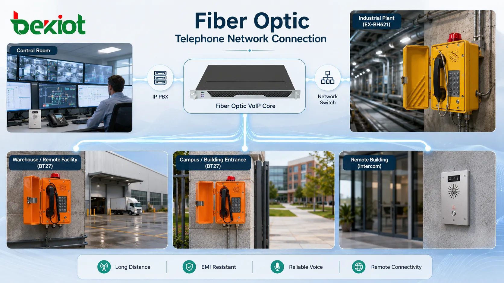
Fiber optic telephones are voice communication endpoints or telephone systems that use fiber-based network transmission as part of the call path. Instead of relying only on copper telephone cables, the voice signal is carried through optical fiber either directly through fiber-enabled equipment or indirectly through media converters, fiber switches, IP PBX systems, gateways, and VoIP platforms.
The main advantage is not that the handset itself must always contain an optical port. In many real projects, the phone may be an IP phone, emergency phone, industrial phone, analog phone through an adapter, or dispatch terminal, while the backbone network uses optical fiber. This design improves distance coverage, reduces electromagnetic interference, supports centralized management, and helps keep voice communication stable across large buildings, campuses, tunnels, factories, stations, and remote facilities.
Why Optical Links Improve Voice Deployment
Traditional copper lines are practical for short runs, but they are affected by distance, electromagnetic noise, grounding differences, surge exposure, and cable aging. In complex sites, long copper runs may introduce hum, attenuation, noise, or unreliable signaling. Fiber changes the transmission environment because it carries information as light through glass or plastic fiber rather than as electrical current through metal conductors.
This gives fiber-based voice systems strong resistance to electromagnetic interference. It is especially useful near motors, transformers, high-voltage equipment, elevators, rail systems, industrial drives, broadcast equipment, welding machines, and lightning-prone outdoor routes.
Fiber also supports long-distance transmission. A voice network can connect remote gates, control rooms, substations, tunnel portals, parking structures, campus buildings, warehouses, and security posts without forcing all devices to stay near the main communication room.
How the Call Path Is Built
Endpoint Layer
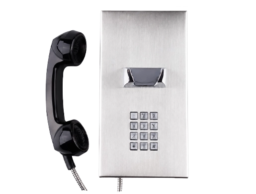
The endpoint layer includes the device users actually speak through. This may be an IP telephone, SIP intercom, analog handset, emergency call station, operator console, elevator phone, or rugged industrial terminal. Some devices connect directly to Ethernet, while others require an analog adapter or gateway.
The endpoint converts the user’s voice into a signal suitable for the local access method. For an IP device, voice is encoded into digital packets. For an analog device, the analog signal must be converted before it can enter the IP or fiber network.
Access Conversion Layer
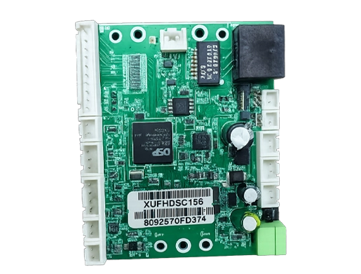
When a device does not have a direct fiber interface, access conversion is used. This may include a media converter, fiber switch, analog telephone adapter, voice gateway, or Ethernet-to-fiber uplink. The role of this layer is to bridge the local device connection to the optical transmission network.
In practical projects, the phone may connect through copper Ethernet for a short distance, while the switch uplink uses fiber to reach the main equipment room. This provides the benefits of fiber without requiring every phone to include an optical module.
Voice Control Layer
The voice control layer handles registration, dialing, routing, call permissions, extensions, voicemail, recording, group calling, emergency routing, and trunk access. It may be an IP PBX, hosted VoIP platform, SIP server, dispatch system, or unified communication platform.
Fiber does not replace call control. It provides the transport path. The PBX or voice platform still decides how calls are routed and how endpoints communicate.
Transmission Layer
The transmission layer includes optical fiber cables, patch panels, optical distribution frames, SFP modules, fiber switches, media converters, and possibly ring-network or redundant backbone equipment. This layer determines distance, bandwidth, link redundancy, and physical reliability.
For clear voice calls, the transmission layer must provide stable packet delivery with controlled latency, jitter, and packet loss.
Where Call Clarity Comes From
Call clarity is the result of several factors working together. Fiber reduces electrical interference and signal degradation over long distances, but audio quality also depends on codec selection, microphone design, speaker quality, echo cancellation, network QoS, packet loss, jitter, endpoint processing, and PBX configuration.
For VoIP systems, voice is typically carried in RTP packets after call setup. If the fiber network is stable, packet loss is low and latency remains predictable. This helps maintain natural conversation quality and reduces choppy audio.
In noisy locations, the phone hardware still matters. A clear optical backbone cannot fix poor microphone placement, weak speaker volume, acoustic echo, wind noise, or a damaged handset. Good deployment combines a clean network path with suitable endpoint selection.
Suitable Project Environments
Large Buildings and Campuses
Office parks, universities, hospitals, public buildings, hotels, and industrial campuses often need voice coverage across many buildings. Fiber links can connect distributed network rooms while keeping call control centralized.
This avoids long copper runs between buildings and reduces grounding problems caused by separate electrical systems.
Tunnels and Transportation Facilities
Metro tunnels, railway stations, highway tunnels, airports, bus terminals, and ports may need telephones at remote points. Fiber is useful because it can cover long distances and resist interference from traction power, signaling systems, machinery, and public infrastructure equipment.
Phones can be placed at emergency points, platforms, equipment rooms, ticketing areas, gates, service corridors, and operation centers.
Industrial and Energy Sites
Factories, refineries, power plants, mines, substations, water treatment facilities, and warehouses often contain strong electrical noise and long cable routes. Fiber helps isolate communication paths from electrical interference and ground potential differences.
In these environments, Becke Telcom can be considered in solution planning when industrial voice terminals, emergency communication points, and fiber-connected VoIP architectures need to work together across harsh or distributed sites.
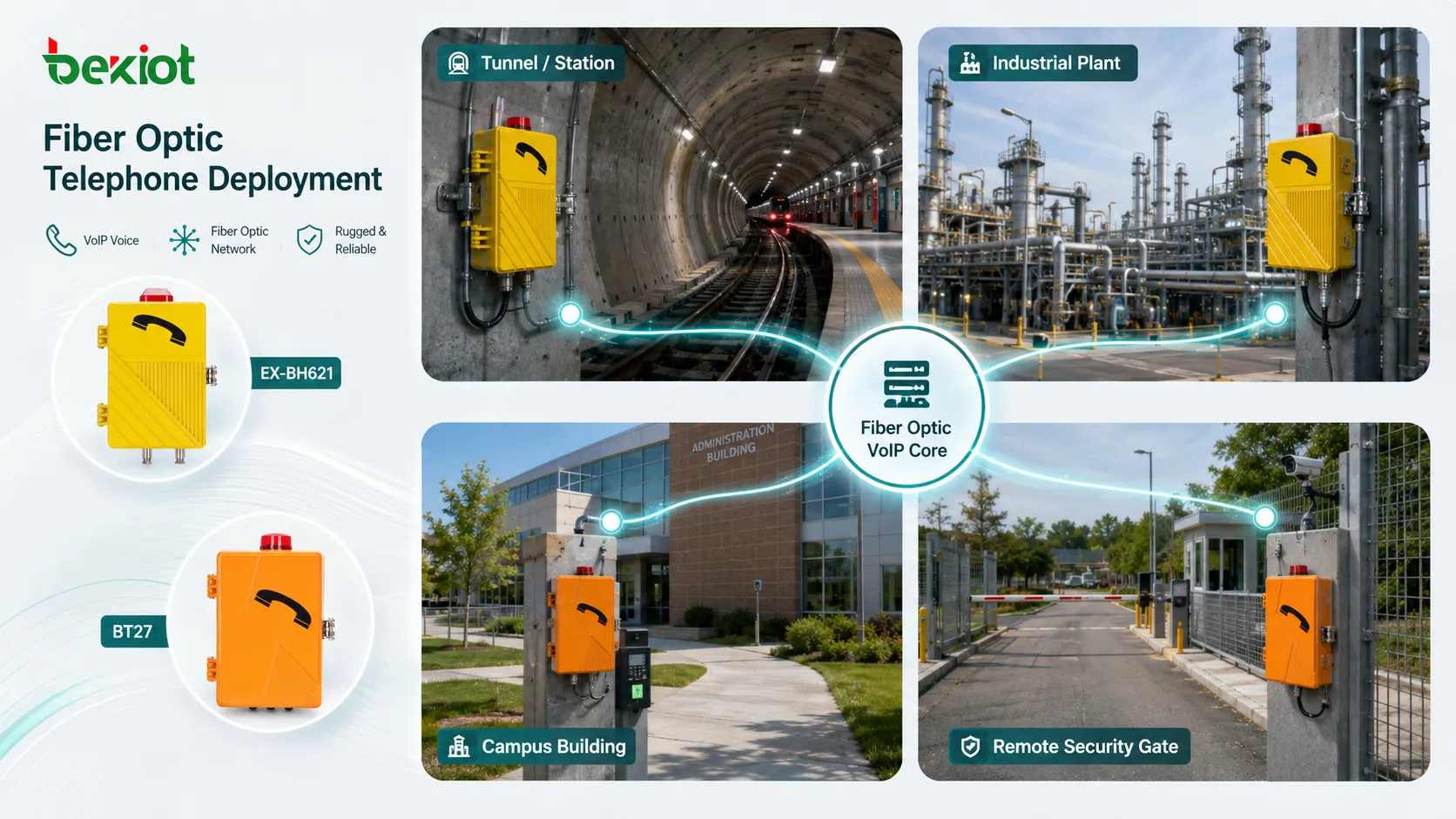
Security and Emergency Communication
Security desks, emergency help points, gate phones, parking assistance terminals, and control room phones may need reliable long-distance connectivity. Fiber helps connect these endpoints to a central command point while reducing the risk of signal quality loss.
When used for emergency communication, the design should also include backup power, clear location labeling, routine testing, and fallback call routing.
Installation Planning Before Cabling
Before installation, the project team should map all communication points. This includes phone locations, network rooms, PBX location, fiber routes, patch panel positions, power sources, equipment cabinets, cable trays, and possible outdoor crossings.
Next, define the system type. Some projects use IP phones over fiber Ethernet networks. Others connect analog phones through gateways. Some use SIP emergency terminals, while others use a hybrid structure with analog and IP devices. The architecture should be chosen before hardware is purchased.
Distance and environment must also be checked. Indoor office fiber, outdoor armored fiber, underground ducts, industrial cable routes, and tunnel installations may require different cable types, protection methods, connectors, and installation practices.
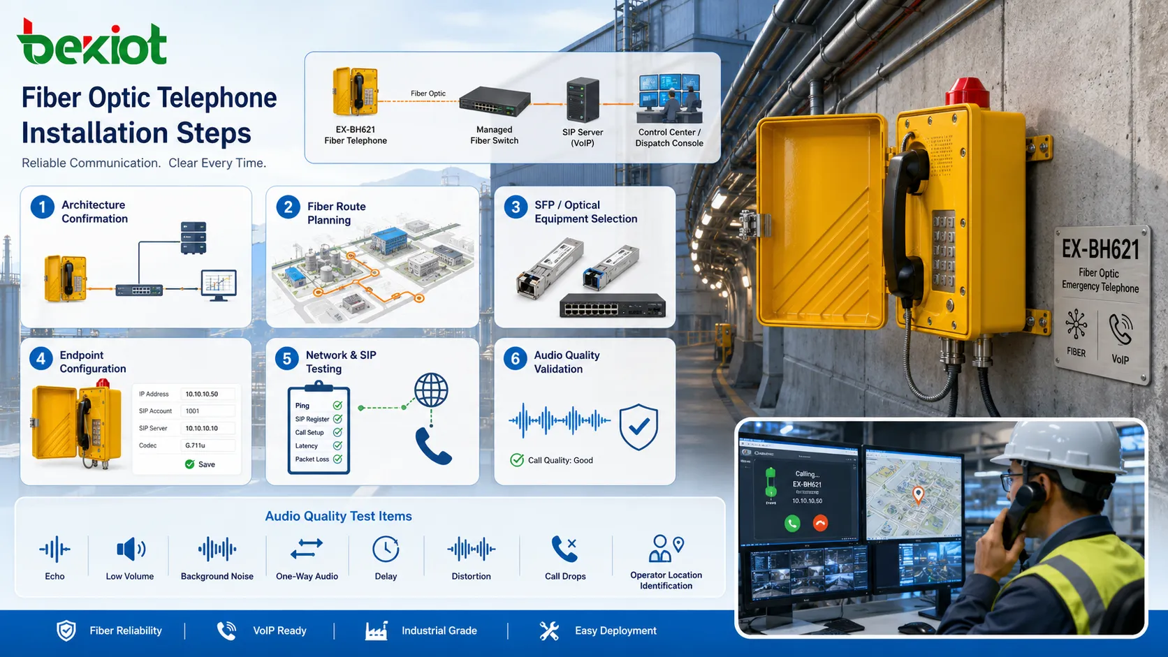
Step-by-Step Installation Process
Step 1: Confirm the Voice Architecture
Decide whether the system will use IP phones, analog phones with adapters, SIP intercoms, fiber-enabled endpoints, or a combination of these. Confirm the PBX or VoIP platform, extension plan, routing rules, and trunk access.
This step prevents mismatched hardware. A fiber cable alone does not define whether the endpoint should be SIP, analog, or gateway-based.
Step 2: Design the Fiber Route
Plan the optical path from the main equipment room to each remote cabinet or endpoint area. Consider distance, bend radius, cable protection, spare cores, patching points, building entry, grounding separation, and physical security.
For outdoor or industrial routes, use cable types suitable for moisture, crushing, rodents, UV exposure, vibration, or mechanical stress where required.
Step 3: Select Optical Equipment
Choose fiber switches, media converters, SFP modules, patch panels, optical distribution frames, and power supplies that match the fiber type and required distance. Single-mode and multimode fiber should not be mixed without proper optical interface planning.
Check connector type, wavelength, speed, optical budget, duplex or simplex requirement, and whether the network needs redundancy.
Step 4: Prepare Voice Endpoints
Configure each phone or terminal with its extension, SIP account, display name, codec settings, call destination, emergency route, VLAN setting, and management access. For analog devices, configure the adapter or gateway port mapping.
Endpoint labels should match physical locations. A phone in “Tunnel Exit 2” should not appear as an unclear extension number at the control room.
Step 5: Connect and Test the Network
After fiber termination and patching, test optical power, link status, VLAN connectivity, switch port configuration, IP addressing, and route reachability. A link light is not enough; packet stability should also be checked.
Voice testing should include internal calls, external calls, emergency calls, group calls, call transfer, voicemail, recording, and fallback routes where applicable.
Step 6: Validate Audio Quality
Test real speech from the final installation position. Check for echo, low volume, background noise, one-way audio, delay, distortion, and call drops. If the environment is noisy, test during normal operating conditions rather than in a quiet commissioning period.
For emergency phones, test whether the operator can clearly hear the caller and identify the location quickly.
Network Settings That Affect Voice Quality
QoS should be configured to prioritize voice packets where the network carries both voice and data. Voice VLANs, DSCP marking, switch priority queues, and controlled uplink capacity can help protect calls during network congestion.
Latency should remain low enough for natural conversation. Fiber itself supports fast transmission, but routing paths, overloaded switches, VPNs, firewalls, or poor WAN links can still create delay.
Jitter control is also important. VoIP endpoints use jitter buffers, but excessive variation can cause choppy audio or increased delay. A stable switched network is better than a congested or poorly segmented network.
Packet loss should be minimized. Even small loss can affect voice clarity, especially with compressed codecs. Network monitoring should watch link errors, optical power margins, port errors, and bandwidth usage.
Power and Backup Considerations
Fiber does not carry power to ordinary phones the way copper PoE Ethernet can. If remote endpoints depend on local switches, converters, or gateways, those devices need reliable power at the remote cabinet or installation point.
For critical communication, backup power is essential. UPS systems, DC power, generator-backed circuits, or redundant power supplies may be required for the PBX, switches, media converters, gateways, and endpoint devices.
Power planning should include the entire call path. A phone may be installed correctly, but communication can still fail if the remote media converter loses power.
Common Faults and Troubleshooting
No Link on Fiber Equipment
If the optical link does not come up, check fiber type, SFP compatibility, transmit and receive polarity, connector cleanliness, optical power level, patch cord condition, and whether the correct wavelength is used.
Single-mode and multimode mismatches are common installation mistakes.
Phone Registers but Audio Fails
This often points to network routing, firewall, VLAN, RTP port, NAT, or gateway configuration problems. SIP registration may work while media traffic is blocked or misrouted.
Packet capture and RTP flow testing can help identify the issue.
Clear Calls Locally but Poor Calls Across Sites
If local calls are clear but remote calls are poor, check inter-site bandwidth, switch uplinks, QoS policy, WAN latency, packet loss, and firewall processing load.
Fiber inside one site cannot compensate for a weak WAN path between sites.
Intermittent Link Drops
Intermittent optical problems may come from dirty connectors, tight bends, damaged patch cords, unstable SFP modules, vibration, high temperature, or marginal optical power.
Cleaning and optical testing should be part of maintenance, especially in industrial and outdoor environments.
Maintenance Practices
Keep fiber connectors clean. Dust and contamination can cause loss or intermittent faults. Use proper fiber cleaning tools and avoid touching connector end faces.
Document all links. Each fiber core, patch panel port, switch port, phone location, endpoint extension, and cabinet should be labeled and recorded. Good documentation shortens troubleshooting time.
Monitor link health. Managed switches can show port status, errors, bandwidth, temperature, and optical diagnostics if supported by the SFP module. These records help detect problems before users report call failure.
Retest after changes. Moving phones, replacing converters, changing VLANs, updating PBX settings, or repatching fiber can affect call behavior. A short functional test should follow every change.
The clarity of a fiber-supported telephone system depends on the whole chain: optical link quality, endpoint hardware, VoIP configuration, power stability, network QoS, and installation discipline.
FAQ
Does a fiber optic telephone always need a direct fiber port?
No. Many deployments use IP phones or analog phones connected to local equipment, while the backbone link between cabinets or buildings uses fiber.
Can fiber improve voice quality by itself?
It can reduce transmission interference and long-distance signal problems, but final call quality also depends on codecs, endpoints, network settings, power stability, and audio environment.
Is single-mode or multimode fiber better for voice systems?
The choice depends on distance, existing infrastructure, optical equipment, and project budget. Single-mode is often used for longer links, while multimode is common in shorter building or data-room links.
What should be tested after installation?
Test optical link quality, IP connectivity, SIP registration, inbound calls, outbound calls, emergency routes, transfer, audio clarity, location display, backup power, and alarm or monitoring functions.
Why does the phone work during normal power but fail during outages?
The remote switch, media converter, gateway, or PBX may not be connected to backup power. Every active device in the call path must be protected if outage operation is required.