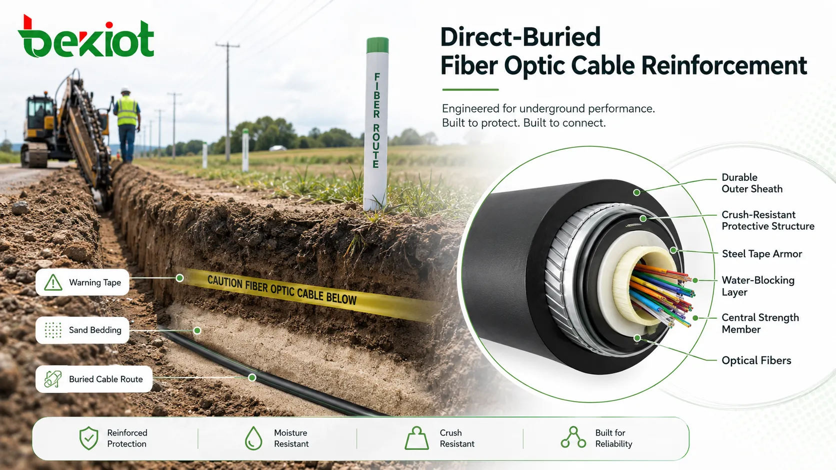
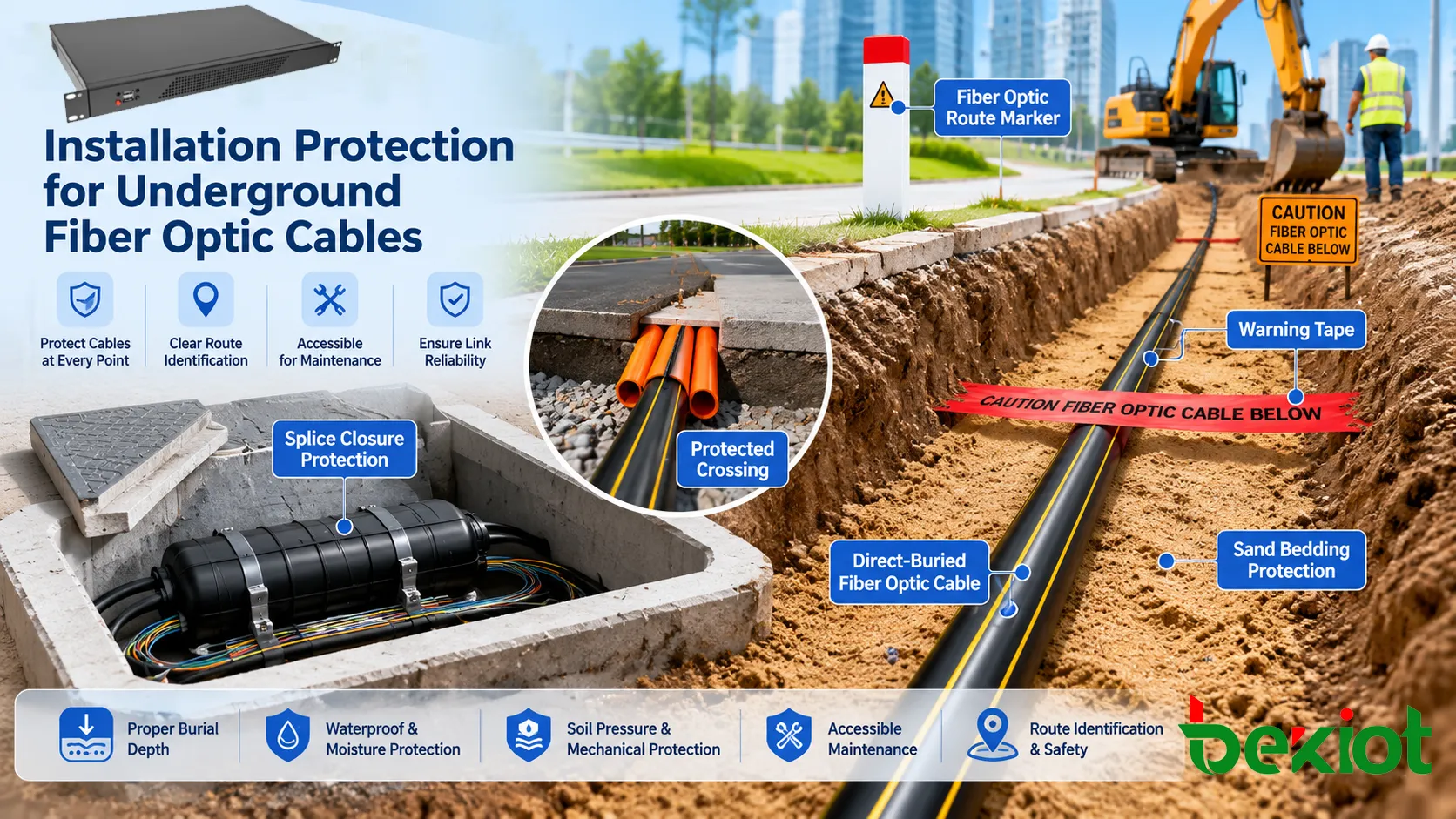
Direct-buried fiber optic cable reinforcement refers to the structural, material, and installation measures used to protect optical fiber cables installed directly in the ground without continuous duct or conduit along the entire route. Because the cable is exposed to soil pressure, moisture, stones, rodents, digging risk, temperature change, and long-term ground movement, reinforcement is essential for maintaining optical performance and service life.
A reinforced underground cable is not simply a normal fiber cable with a thicker jacket. It is a complete protective design that may include water-blocking materials, strength members, armor layers, crush-resistant structure, rodent protection, corrosion-resistant metallic or non-metallic elements, durable outer sheath, warning tape, route markers, proper trench bedding, and tested acceptance procedures. The right reinforcement method depends on soil condition, burial depth, pulling method, mechanical risk, moisture exposure, and the importance of the communication link.
Why Underground Routes Need Stronger Protection
Underground installation may look safer than aerial installation because the cable is hidden from wind and sunlight. In reality, soil creates a different set of risks. A cable may be pressed by compacted earth, squeezed by rocks, damaged by construction tools, attacked by rodents, pulled during settlement, or affected by water that remains around the sheath for many years.
Unlike cables installed in ducts, a direct-buried cable has limited physical separation from the surrounding environment. If the jacket is damaged, soil moisture can reach inner layers. If the cable is crushed, the optical fibers may experience microbending or macrobending loss. If route marking is poor, future excavation may cut the link without warning.
Reinforcement therefore has two goals. The first is to protect the cable body from mechanical and environmental stress. The second is to make the route safer to install, identify, maintain, and repair throughout its service life.
Protective Layers Inside the Cable
Outer Sheath
The outer sheath is the first barrier against soil, moisture, abrasion, and handling damage. Common sheath materials include polyethylene and other outdoor-rated compounds. The sheath should resist cracking, environmental aging, and mechanical wear during pulling, laying, and backfilling.
For direct burial, sheath thickness and material quality are important. A weak sheath may be cut by sharp stones, scraped during installation, or degraded by long-term ground conditions. In harsh environments, the sheath may need enhanced abrasion resistance, chemical resistance, or termite resistance depending on local site risk.
Armor Layer
Armor is one of the most common reinforcement methods for underground optical cables. It may use corrugated steel tape, steel wire, aluminum tape, or non-metallic armor depending on the application. Armor improves resistance to crushing, impact, digging damage, and rodent attack.
Metallic armor provides strong mechanical protection but may require bonding, grounding, corrosion consideration, and lightning protection planning. Non-metallic armor avoids electrical conductivity and may be preferred in areas where grounding complexity, corrosion, or electromagnetic concerns are important.
Strength Member
Strength members help the cable withstand pulling tension and long-term strain. They may be made of steel wire, aramid yarn, glass yarn, fiberglass reinforced plastic, or other materials. Their role is to carry mechanical load so that the optical fibers are not stretched beyond safe limits.
The strength member must match the installation method. A cable pulled through a long route, placed by plowing, or installed across uneven ground may need stronger tensile performance than a short hand-laid section.
Water-Blocking Material
Water blocking prevents moisture from traveling along the cable core if the sheath is damaged. This may be achieved through filling gel, dry water-swellable yarns, water-blocking tapes, or other moisture-blocking structures.
Dry water-blocking materials are often easier to handle during splicing because they reduce gel cleaning work. Gel-filled designs may provide strong water resistance but can be messier during field termination. The choice depends on cable design, installer preference, and project requirements.
Loose Tube and Fiber Protection
Many outdoor fiber cables use loose tube construction. Optical fibers are placed inside tubes that allow controlled movement and protect fibers from direct external stress. This design helps reduce strain transfer from the cable sheath to the glass fibers.
The tube structure, filling material, fiber count, buffer design, and central strength arrangement all affect long-term performance. Reinforcement should protect the optical fibers without making the cable too stiff for practical installation.
A reliable underground cable is built from multiple layers of defense. The outer jacket protects against the soil, the armor resists mechanical attack, the strength member carries tension, and water blocking limits moisture migration.
Mechanical Reinforcement Methods
Steel Tape Armor
Corrugated steel tape armor is widely used for direct-buried fiber optic cables. The corrugated structure improves flexibility while providing resistance to crushing and external impact. It also offers a physical barrier against rodents and accidental tool contact.
Steel tape armor is suitable for many general underground routes, but it should be protected against corrosion. The cable sheath must remain intact, and installation should avoid damaging the jacket. If the route has high soil corrosivity, the cable design and metallic protection requirements should be reviewed carefully.
Steel Wire Armor
Steel wire armor provides strong tensile and mechanical protection, especially for demanding routes, unstable ground, steep slopes, river crossings, and installations where pulling or external load may be higher. It can improve resistance to stretching and localized pressure.
The drawback is increased weight, larger bending radius, and more demanding handling. Installation teams must follow manufacturer limits for pulling tension and bending radius to avoid damaging the cable.
Non-Metallic Reinforcement
Non-metallic reinforcement may include aramid yarn, glass yarn, fiberglass rods, or reinforced polymer layers. These materials can improve tensile strength and rodent resistance without creating a conductive metallic path.
This is useful in power utility environments, lightning-prone areas, railway corridors, or locations where grounding metallic armor is difficult. Non-metallic designs may also reduce corrosion concerns, but mechanical strength must still match the route conditions.
Double Jacket Construction
Some direct-buried designs use double jackets or additional protective layers. A second jacket can improve abrasion resistance, moisture protection, and mechanical durability. It may also help isolate armor from the environment.
Double jacket construction can increase cable diameter and stiffness. Designers should confirm that the cable can still be installed within bend radius, pulling, and joint closure requirements.
Rodent-Resistant Design
Rodent damage is a common risk in rural, agricultural, forest, and utility corridors. Reinforcement may include metallic armor, glass yarn, hard polymer layers, or special sheath materials designed to discourage chewing.
No design should be assumed completely immune in all conditions. If rodent activity is high, route selection, depth, protective board, conduit at vulnerable sections, and inspection strategy should also be considered.
Route-Level Protection Measures
Strong cable construction is only part of the solution. Direct burial also depends on route engineering. Poor trench preparation can damage even a high-quality cable. Proper bedding, backfill, depth, separation, warning tape, and route marking are critical for long-term protection.
In many projects, the most serious failures are caused by installation mistakes rather than cable manufacturing defects. Sharp stones under the cable, excessive pulling force, tight bends, poor compaction, missing warning tape, or undocumented routes can all create future problems.
Route-level protection should be planned before cable delivery. The project should define trench depth, bedding material, crossing methods, road protection, marker posts, slack storage, joint box locations, and as-built documentation requirements.
Trench Design and Installation Requirements
Burial Depth
Burial depth should follow local codes, project specifications, utility owner requirements, and site risk assessment. Areas with vehicle loading, agricultural activity, road crossings, or future construction risk may require deeper burial or additional mechanical protection.
Depth should not be treated as a single universal number. A cable under a sidewalk, green area, highway shoulder, industrial yard, or rail corridor may need different protection. Designers should confirm local requirements before construction.
Bedding and Backfill
The cable should be placed on suitable bedding material that does not contain sharp stones, construction debris, metal fragments, or hard objects. Sand or screened soil is often used to reduce point pressure on the cable jacket.
Backfill should be placed carefully. Directly dropping large stones or compacting aggressively over the cable can damage the sheath or deform the cable structure. Compaction should follow civil requirements while protecting the cable from excessive localized pressure.
Warning Tape and Route Markers
Warning tape is installed above the cable to alert future excavators before they reach the cable depth. In some routes, detectable tape, marker posts, electronic markers, or tracer wires may be used to improve route locating.
Route markers are especially important in long-distance, rural, industrial, and utility corridors. A buried cable without clear records and markers is much more vulnerable to accidental damage during later construction.
Crossings and High-Risk Sections
Road crossings, railway crossings, drainage channels, building entrances, bridge approaches, and utility intersections often require additional protection. Even if most of the route is direct buried, these sections may use conduit, steel pipe, concrete protection, directional drilling, or protective slabs.
Crossing design should consider load, vibration, settlement, access for repair, and future excavation. The cable should not be forced into sharp bends at entry and exit points.
Slack and Joint Protection
Slack loops and joint closures must be protected from water, soil pressure, and mechanical damage. Joint pits, handholes, splice closures, and transition points should be installed so they remain accessible for maintenance.
Poorly protected joints often become weak points. Even if the cable span is well reinforced, a damaged splice closure or flooded joint box can interrupt the entire link.
Standard and Testing Considerations
Mechanical Performance
Direct-buried cables are usually evaluated for tensile strength, crush resistance, impact resistance, repeated bending, torsion, and abrasion-related performance. These tests help verify whether the cable can survive installation and long-term underground stress.
The required values should come from the project specification, cable standard, and manufacturer datasheet. A cable suitable for ordinary outdoor duct use may not have enough crush or impact resistance for direct burial.
Water Penetration
Water penetration testing verifies whether water can travel along the cable core under defined conditions. This is important because a small sheath damage point can become a long-distance moisture problem if water migrates inside the cable.
For underground routes, water-blocking performance should be reviewed together with sheath quality, joint sealing, closure protection, and cable end sealing. The whole link must prevent moisture movement, not only the factory cable length.
Temperature and Environmental Aging
Outdoor cables may be tested for temperature cycling, low-temperature bending, high-temperature operation, and material aging. Soil temperature changes are usually less extreme than exposed aerial routes, but underground cables may still face seasonal variation, freeze-thaw conditions, or heat from nearby utilities.
Environmental testing should match the local climate and installation conditions. Cold-region burial, desert soil, chemical plant areas, and coastal ground conditions may require different material attention.
Optical Performance
Reinforcement must not compromise optical performance. After mechanical and environmental testing, attenuation should remain within acceptable limits. Excessive pressure, bending, or tensile strain can cause increased loss even when the cable appears physically intact.
Acceptance testing should include optical time-domain reflectometer testing, insertion loss testing, end-face inspection, and comparison with design budgets. Test results should be stored as baseline records for future troubleshooting.
Bonding and Grounding
If the cable includes metallic armor, metallic strength members, tracer wire, or conductive shielding, bonding and grounding requirements should be reviewed. Metallic elements may create lightning, fault current, induced voltage, or safety considerations depending on the route.
Grounding design should follow applicable electrical and telecommunications codes. Non-metallic cable may reduce these concerns, but it may still need locating solutions if the route must be traceable later.
Material Selection Guide
| Condition | Recommended Reinforcement Focus | Reason |
|---|---|---|
| Rocky soil | Strong outer sheath, armor layer, good bedding, screened backfill. | Reduces point pressure, jacket cuts, and crush damage. |
| High moisture area | Water-blocking core, sealed joints, moisture-resistant sheath. | Limits water migration and protects optical performance. |
| Rodent-prone route | Metallic armor, glass yarn, hard sheath, protected vulnerable sections. | Improves resistance to chewing and animal damage. |
| Power corridor | Non-metallic reinforcement or carefully bonded metallic design. | Reduces electrical risk or manages conductive elements safely. |
| Road crossing | Conduit, protective pipe, deeper burial, reinforced transition points. | Handles load, vibration, and future excavation risk. |
Applications in Outdoor Networks
Telecom Access Routes
Direct-buried reinforced cable is used in access networks where duct construction is not practical or cost-effective. It can connect rural users, small settlements, roadside cabinets, base station sites, and remote service points.
In these routes, reinforcement reduces the risk of soil pressure, moisture ingress, and accidental damage. Clear route marking and as-built records are especially important because future excavation may occur long after installation.
Industrial and Utility Corridors
Industrial parks, mines, power plants, oil and gas sites, water treatment facilities, and utility corridors often require robust underground communication links. These environments may involve heavy vehicles, chemical exposure, vibration, and repeated maintenance work.
Reinforcement should be combined with route planning. Cables should avoid high-risk excavation zones where possible, and protected crossings should be used near roads, pipe racks, cable trenches, and equipment yards.
Transportation Infrastructure
Railways, highways, tunnels, ports, and airports use underground fiber for signaling, surveillance, communication, control, ticketing, and monitoring systems. Service interruption can affect safety and operations.
These projects often need stricter installation control, route documentation, spare ducts at crossings, and clear separation from power, drainage, and other utilities.
Campus and Enterprise OSP Networks
Large campuses, factories, hospitals, universities, logistics parks, and government facilities may use direct-buried fiber between buildings or remote outdoor cabinets. Customer-owned outside plant networks require careful planning because the organization may be responsible for both installation and long-term maintenance.
In campus environments, reinforced cable should be selected together with pathway design, grounding policy, maintenance access, labeling, and network redundancy.
Common Installation Mistakes
Using Non-Burial Cable
A cable intended for indoor or duct installation should not be buried directly unless the manufacturer and project specification clearly allow it. Non-burial cable may lack armor, water blocking, crush resistance, or suitable sheath material.
Using the wrong cable type can reduce service life and make warranty or acceptance difficult.
Ignoring Bend Radius
Reinforced cables can be stiffer than ordinary cables. If installers force the cable around sharp bends, optical loss may increase or internal structures may be damaged.
Minimum bend radius should be respected during pulling, laying, jointing, and final placement.
Poor Trench Preparation
Sharp stones, uneven trench bottoms, debris, and poor bedding can damage the cable immediately or create pressure points that cause long-term failure.
The trench should be inspected before cable placement, and backfill should be controlled around the cable zone.
Missing Route Records
A cable can be well installed but still be lost to future excavation if records are poor. Missing route maps, marker posts, warning tape, or detectable elements create unnecessary repair risk.
As-built drawings should record cable path, depth, joint positions, crossing points, markers, and slack locations.
Weak Joint Protection
Joints, closures, and branch points are common failure locations. If they are not sealed, supported, and accessible, moisture and mechanical stress may cause future outages.
Joint protection should be treated as part of the cable reinforcement strategy, not as a separate afterthought.
The strongest cable can still fail if the trench, bedding, joint protection, route marking, and acceptance testing are poorly managed.
Acceptance and Documentation
After installation, the route should be inspected before final acceptance. The inspection may include trench records, burial depth checks, warning tape confirmation, marker verification, joint closure inspection, cable entry sealing, and route documentation review.
Optical testing should establish a baseline. OTDR traces, insertion loss results, fiber identification, splice loss, connector inspection, and end-to-end continuity records should be saved for future maintenance. These records help technicians compare future faults against the original condition.
Documentation should include cable type, fiber count, reel numbers, route drawings, joint locations, slack storage, test results, grounding records, and any deviations from the original design. Good documentation reduces repair time when damage occurs years later.
Maintenance and Long-Term Reliability
Direct-buried routes require periodic review even when they operate normally. Maintenance teams should monitor route changes, nearby construction, soil erosion, flooding, road expansion, utility work, and unauthorized excavation activity.
If a route crosses high-risk areas, marker posts and warning signs should be inspected regularly. After major civil work near the route, the fiber link should be tested to confirm that optical performance has not changed.
For critical networks, route diversity is important. Reinforced cable reduces failure probability, but it cannot eliminate all risk. A second path, ring topology, or backup communication route may be needed when service continuity is essential.
FAQ
Can a duct cable be used for direct burial?
Only if the cable manufacturer and project specification confirm that the cable is rated for direct burial. Many duct cables do not have enough armor, water blocking, or crush resistance for direct soil contact.
Is metallic armor always better than non-metallic protection?
No. Metallic armor offers strong mechanical and rodent protection, but it may require grounding and corrosion planning. Non-metallic designs may be better where electrical isolation or corrosion resistance is more important.
What causes optical loss after burial?
Common causes include excessive bending, crushing, pulling beyond rated tension, poor bedding, sharp stones, joint stress, water ingress, or cable movement after backfilling.
Why is warning tape needed if the cable is already armored?
Armor can reduce damage risk, but it does not stop an excavator from cutting the route. Warning tape alerts workers before they reach the cable and reduces accidental strike risk.
What records should be kept after installation?
Keep as-built route drawings, burial depth records, joint locations, cable datasheets, reel numbers, grounding details, OTDR traces, insertion loss results, splice records, and marker location information.