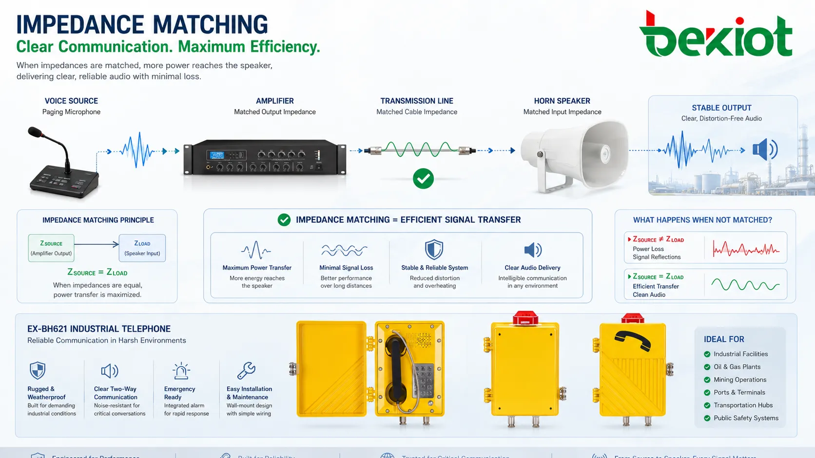
Impedance is the opposition that an electrical circuit presents to alternating current. In practical communication and audio systems, it affects how signals travel through cables, speakers, microphones, antennas, telephone circuits, amplifiers, transmission lines, and electronic interfaces. When impedance is correctly matched, more useful signal energy reaches the load. When it is poorly matched, the system may suffer from signal loss, reflection, distortion, low volume, overheating, unstable operation, or reduced transmission distance.
Although impedance is a basic electrical concept, it becomes very practical during deployment. It helps engineers choose the right cable, connect speakers safely, match microphones and amplifiers, avoid overloading outputs, troubleshoot weak signals, and maintain reliable voice, paging, intercom, radio, and industrial communication systems.
Why Impedance Matters During Deployment
It affects signal strength and system stability
In a communication system, every connected part influences the signal path. A microphone sends a small signal to a preamplifier, a line output drives a cable, an amplifier powers a speaker, and an antenna connects to a transmitter through a coaxial line. Each connection has an expected impedance range. If the connected equipment does not match that range, the signal may become weaker, noisier, or less stable.
This is why impedance is not only a laboratory measurement. It is a deployment factor. A system may look correct on a wiring diagram but perform poorly on site if the cable length, speaker load, terminal wiring, transformer tap, or input/output impedance is wrong.
It helps prevent equipment overload
Incorrect impedance can create excessive current or an unsuitable load for an amplifier, transmitter, or output circuit. For example, connecting too many low-impedance speakers in parallel may reduce the total load impedance beyond what the amplifier can safely drive. The result may be overheating, protection shutdown, distorted sound, or permanent damage.
In field projects, this often happens when a system is expanded without recalculating the total load. Adding more speakers, extending cable runs, replacing devices with different ratings, or mixing equipment from different systems should always be checked against the permitted impedance or power-loading range.
How Impedance Works in Simple Terms
Resistance, reactance, and frequency
Resistance is opposition to direct current, while impedance applies to alternating current and signal circuits. Impedance includes resistance and reactance. Reactance comes from capacitors and inductors, and it changes with frequency. This is why impedance is usually written in ohms, but it is not always the same as a simple DC resistance reading.
A speaker marked 8 ohms, for example, does not maintain exactly 8 ohms at every frequency. Its impedance changes across the audio range. A transmission line or antenna system may also behave differently depending on frequency, cable type, connector quality, and installation conditions.
Matching and bridging are not the same
In some systems, the goal is impedance matching. This is common in RF transmission lines and certain audio distribution designs, where the source, cable, and load should be matched to reduce reflections and maximize power transfer. In other systems, such as many modern audio inputs, the design uses impedance bridging. The input impedance is much higher than the source impedance, allowing voltage transfer without heavily loading the source.
Understanding the system type matters. Applying one rule to every audio, telephone, or RF circuit can lead to mistakes. A speaker output, a microphone input, a line-level input, a 70V/100V distributed speaker system, and a coaxial antenna line all need different impedance thinking.
Impedance is not only a number on a datasheet. It describes how a real signal behaves when equipment, cable, frequency, distance, and load are connected together.
Key Features to Check in Real Systems
Input and output impedance
Input impedance describes how much load a device presents to the signal source. Output impedance describes how the source behaves when driving a connected load. In audio and communication systems, the relationship between these values affects level, clarity, noise pickup, and compatibility.
When replacing equipment, engineers should compare the old and new impedance specifications. A device with the same connector type may still have a different electrical behavior. This is especially important for microphones, analog telephone interfaces, paging amplifiers, radio accessories, and legacy control circuits.
Cable impedance and transmission quality
Cables are not just conductors. They have capacitance, inductance, resistance, shielding behavior, and characteristic impedance. In short cable runs at low audio frequencies, some effects may be small. In long runs, high-frequency signals, RF systems, video links, and data transmission, cable impedance becomes much more important.
Coaxial systems often use standard impedance values such as 50 ohms or 75 ohms depending on the application. Twisted-pair and network cabling also have controlled impedance characteristics. Using the wrong cable type may increase reflection, attenuation, noise susceptibility, and connection instability.
Load impedance and power handling
Load impedance is critical for speakers, amplifiers, and distributed audio systems. A low impedance load draws more current from the amplifier. A high impedance load may reduce output power. If the system is not designed correctly, sound coverage may become uneven or the amplifier may operate outside its safe range.
For paging and public address systems, designers often use transformer-based 70V or 100V distribution to simplify long cable runs and multi-speaker connections. In this type of system, power tap settings are usually more important for load calculation than the nominal speaker impedance alone.
| System Area | Impedance Concern | Possible Problem If Ignored |
|---|---|---|
| Speaker circuits | Total load impedance or transformer tap load | Amplifier overload, low volume, distortion, or shutdown |
| Microphone inputs | Source and input compatibility | Weak signal, high noise, dull sound, or poor pickup |
| RF transmission | Cable, antenna, and transmitter matching | Reflections, poor range, high VSWR, or transmitter stress |
| Telephone interfaces | Line impedance and hybrid balance | Echo, low level, unstable call quality, or poor DTMF detection |
| Long cable runs | Cable impedance, capacitance, and loss | Signal attenuation, noise pickup, and reduced clarity |
| Replacement devices | Input/output rating differences | Unexpected incompatibility despite similar connectors |
Deployment Benefits of Correct Impedance Planning
More predictable audio and signal performance
Correct impedance planning improves predictability. Speakers receive the expected power, microphones deliver usable levels, antennas radiate more efficiently, and line signals travel with less loss. This helps the deployed system behave closer to the design plan.
For integrators, this reduces repeated adjustments after installation. Instead of trying to solve weak sound or unstable transmission by increasing gain, replacing devices, or adding extra amplifiers, the system can be built correctly from the beginning.
Lower risk of equipment damage
A system with suitable load impedance puts less stress on amplifiers, transmitters, output drivers, and power stages. This is important for equipment that works continuously, such as paging amplifiers, dispatch audio channels, radio repeaters, emergency call systems, and industrial control interfaces.
Long-term reliability depends on electrical loading as well as environmental protection. Even rugged devices can fail early if they are repeatedly forced to drive the wrong load or operate under high heat caused by incorrect impedance.
Cleaner troubleshooting and maintenance
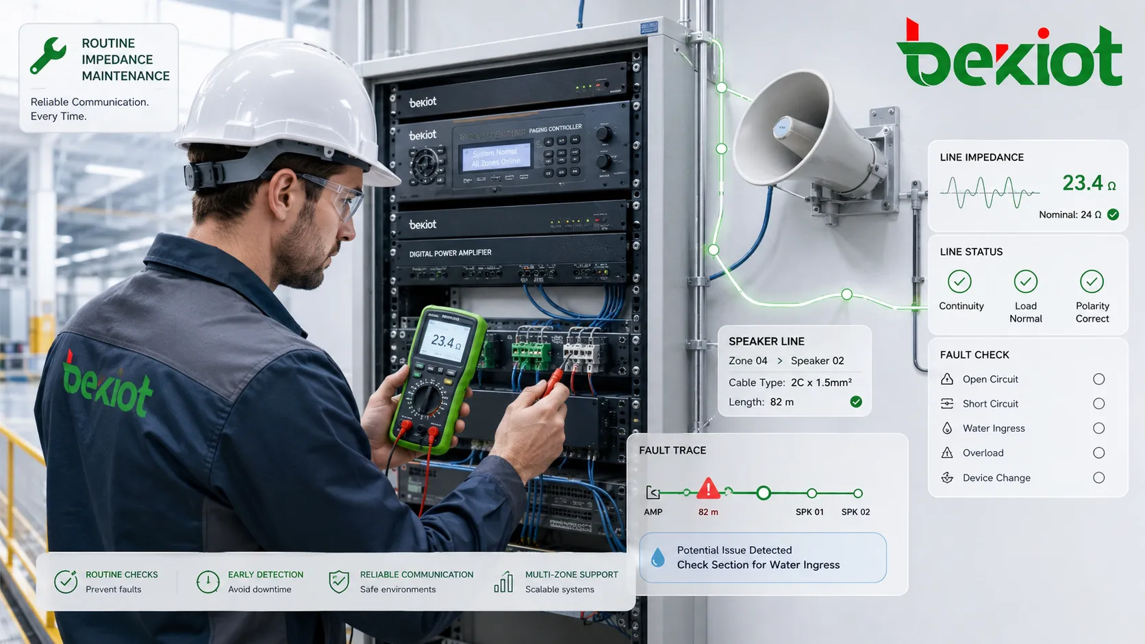
When impedance is documented and measured properly, maintenance teams can troubleshoot problems more quickly. A sudden change in line impedance may indicate a broken cable, water ingress, loose connector, damaged speaker, short circuit, wrong replacement part, or unauthorized field modification.
This is especially useful in large buildings, industrial facilities, transportation sites, campuses, and multi-zone paging systems. Instead of checking every endpoint blindly, technicians can use measurements to narrow down the fault location.
Maintenance Tips for Reliable Operation
Measure before and after changes
Any system expansion should include impedance verification. When adding speakers, changing amplifiers, replacing microphones, extending cables, or modifying antenna lines, technicians should compare the measured values with the design requirement and equipment rating.
This simple step prevents many common failures. It is better to find an overload condition during commissioning than after the amplifier shuts down during an emergency announcement or production call.
Keep a record of baseline values
A baseline record is useful for future maintenance. After commissioning, technicians can record speaker line impedance, cable test results, RF measurements, amplifier load calculations, and input/output settings. Later inspections can compare new readings against the baseline.
If the value changes significantly, the team can investigate before users report poor audio or intermittent faults. This is a practical way to move from reactive repair to preventive maintenance.
Check connectors, moisture, and corrosion
Many impedance-related faults are caused by physical installation problems. Loose terminals, oxidized connectors, water inside junction boxes, damaged cable insulation, crushed cable, wrong adapters, and poor shielding can all change how the circuit behaves.
Outdoor systems and industrial environments need special attention. Moisture and corrosion may not cause a complete failure immediately, but they can gradually create leakage paths, intermittent noise, and unstable impedance readings.
Do not mix equipment without recalculation
Mixing devices with different ratings can create hidden problems. For example, replacing one speaker with a lower-impedance model may change the total amplifier load. Adding a parallel branch to an existing speaker circuit may reduce impedance below the safe limit. Installing a non-matching antenna or coaxial cable may reduce RF efficiency.
Before field teams replace parts, the maintenance procedure should define approved models, ratings, tap settings, cable types, and test requirements. This avoids gradual system degradation after multiple small repairs.
Applications in Communication and Electrical Systems
Public address and paging systems
In public address and paging systems, impedance affects amplifier loading, speaker volume, cable distance, and zone reliability. Low-impedance speaker systems are often used for shorter runs or local audio, while 70V/100V systems are common for distributed paging across larger sites.
Correct load calculation ensures that the amplifier can drive all connected speakers without overload. It also helps designers balance sound coverage across offices, workshops, corridors, platforms, warehouses, and outdoor areas.
Intercoms, emergency phones, and dispatch audio
Intercom and emergency communication systems include microphones, speakers, handsets, amplifiers, analog interfaces, and sometimes long cable runs. Impedance compatibility helps maintain speech clarity, volume stability, and reliable two-way communication.
In dispatch environments, a poorly matched endpoint may create low-level audio, echo, or noise that affects the operator’s ability to understand the caller. This is why audio path design should be checked from the field device to the control room platform.
RF, antenna, and radio systems
RF systems are highly sensitive to impedance matching. Transmitters, coaxial cables, connectors, splitters, lightning protectors, and antennas must be selected and installed according to the required impedance. Mismatch can cause reflected power, reduced coverage, high VSWR, and additional stress on the transmitter.
Regular inspection of connectors, grounding, water sealing, and antenna condition is important. A small connector problem can create a large performance issue at radio frequencies.
Telephone lines and legacy interfaces
Traditional telephone systems and analog interfaces rely on line impedance for correct audio balance and signaling behavior. Poor impedance matching may contribute to echo, weak audio, crosstalk, or unstable signal detection. This is still relevant when legacy analog circuits connect to modern gateways, PBX systems, recording devices, or dispatch platforms.
During migration from analog to IP-based systems, engineers should not only check protocol compatibility. They should also verify analog port impedance, line length, wiring condition, and audio level to ensure stable operation.
Common Mistakes to Avoid
Using DC resistance as the only judgment
A multimeter resistance reading can help find open circuits or shorts, but it does not fully describe impedance under operating frequency. Speakers, transformers, cables, and antennas may behave differently when actual audio or RF signals are present.
For accurate diagnosis, technicians should use the correct test method for the system type. Speaker impedance meters, audio analyzers, line testers, and antenna analyzers provide more useful information than a simple DC resistance check in many cases.
Ignoring cable length and routing
A circuit that works on a short test bench may fail over a long route. Cable resistance, capacitance, shielding, grounding, and routing near power equipment can affect the final result. Long cable paths should be designed with both electrical loading and environmental exposure in mind.
Good practice includes proper cable selection, clear labeling, separation from high-power lines where required, weatherproof termination, and testing at the final installed length rather than only at the equipment room.
Conclusion
Impedance is a practical deployment and maintenance concept for communication, audio, RF, telephone, and industrial electronic systems. It influences signal transfer, equipment loading, audio clarity, transmission distance, troubleshooting accuracy, and long-term reliability.
For successful projects, impedance should be considered during design, installation, expansion, and maintenance. By matching equipment correctly, calculating loads, choosing suitable cable, recording baseline measurements, and testing after changes, engineers can build systems that remain stable, clear, and easier to maintain over time.
FAQ
Why does a speaker marked 8 ohms not measure exactly 8 ohms with a multimeter?
The 8-ohm value is a nominal impedance rating for audio operation, not a fixed DC resistance value. A multimeter measures DC resistance, which is usually lower than the rated impedance and does not show how the speaker behaves across the audio frequency range.
Can incorrect impedance cause intermittent faults instead of immediate failure?
Yes. Some impedance problems appear only when volume increases, temperature changes, moisture enters a cable joint, or several devices operate together. This can cause intermittent distortion, shutdown, noise, or unstable transmission rather than a complete failure.
Is higher impedance always safer for equipment?
Not always. A higher load impedance may reduce current demand, but it can also reduce available power or create poor signal transfer in systems that require matching. The correct value depends on the equipment design and application.
What tool is commonly used to test speaker line impedance?
A dedicated speaker line impedance meter is commonly used because it tests the circuit in a way that is more relevant to audio systems than a basic DC resistance meter. For 70V/100V systems, technicians should also check total wattage load and transformer tap settings.
Can impedance issues affect audio recording quality?
Yes. If a microphone, line interface, or telephone audio path is poorly matched, the recorded signal may be weak, noisy, distorted, or unbalanced. This can reduce the usefulness of recordings for review, training, or incident analysis.
Should impedance be checked during preventive maintenance?
Yes. Periodic checks can reveal cable degradation, water ingress, loose connections, wrong replacements, speaker failure, or load changes before users notice poor performance. Baseline values from commissioning make these checks much more useful.