In 5G NR, carrier bandwidth can be configured across a wide range. The minimum bandwidth can be as small as 5MHz, while the maximum supported bandwidth can reach 400MHz. This wide bandwidth design gives 5G networks strong capacity potential, but it also creates practical challenges for user equipment, especially when different terminals have different hardware capabilities, cost targets, and power consumption limits.
If every UE had to support the full carrier bandwidth all the time, device complexity would increase significantly. Wider bandwidth requires higher sampling rates, stronger baseband processing capability, larger RF bandwidth support, and more energy consumption. For many terminals, especially cost-sensitive devices, IoT terminals, industrial data units, and future RedCap-type devices, full-bandwidth operation is unnecessary for most service scenarios.
Why Wide Carrier Bandwidth Needs Better Control
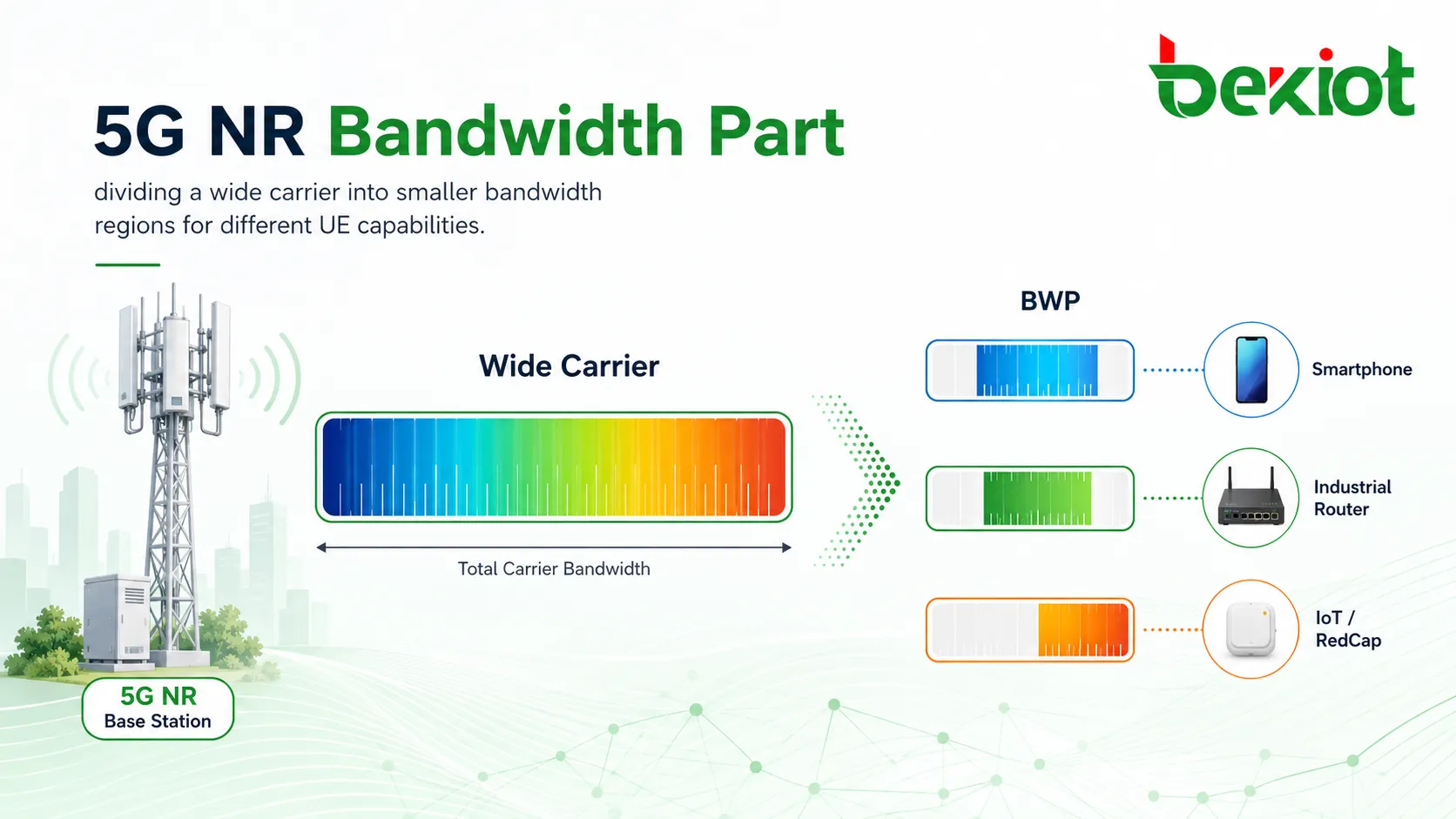
A 5G cell may provide a wide carrier, but not every device needs to monitor or transmit across the entire frequency range. A high-performance smartphone, an industrial router, a low-cost terminal, and a reduced-capability device may all connect to the same network, but their bandwidth requirements are very different.
For network planning, this creates two major issues. The first is device cost. When a UE supports wider bandwidth, its RF front end, baseband processing, filtering, and sampling capability become more demanding. The second is power consumption. Wideband reception and transmission usually require higher sampling rates, and higher sampling rates increase power usage.
Bandwidth Part, commonly shortened as BWP, was introduced to solve these problems. Instead of requiring a UE to work across the entire carrier bandwidth, the network can configure a smaller continuous section of bandwidth for that UE. The terminal can then operate only within the configured range while still being part of the larger 5G NR cell.
The Basic Concept Behind BWP
A Bandwidth Part is a continuous set of physical resource blocks configured by the base station for a UE. It is not a separate cell. It is a usable bandwidth region inside the serving carrier. The network can configure different BWPs according to UE capability, service demand, cell strategy, and radio resource conditions.
For example, an NR cell may have 30MHz of carrier bandwidth. If a terminal supports only 20MHz in that frequency band, the base station can configure a 20MHz BWP for that terminal. In this way, the UE does not need to support the full cell bandwidth, but it can still access the network and use services within its supported range.
This mechanism gives operators and system designers more flexibility. A single wideband 5G cell can serve high-capacity users, lower-cost terminals, and service-specific devices at the same time, instead of forcing all devices to use the same bandwidth capability.
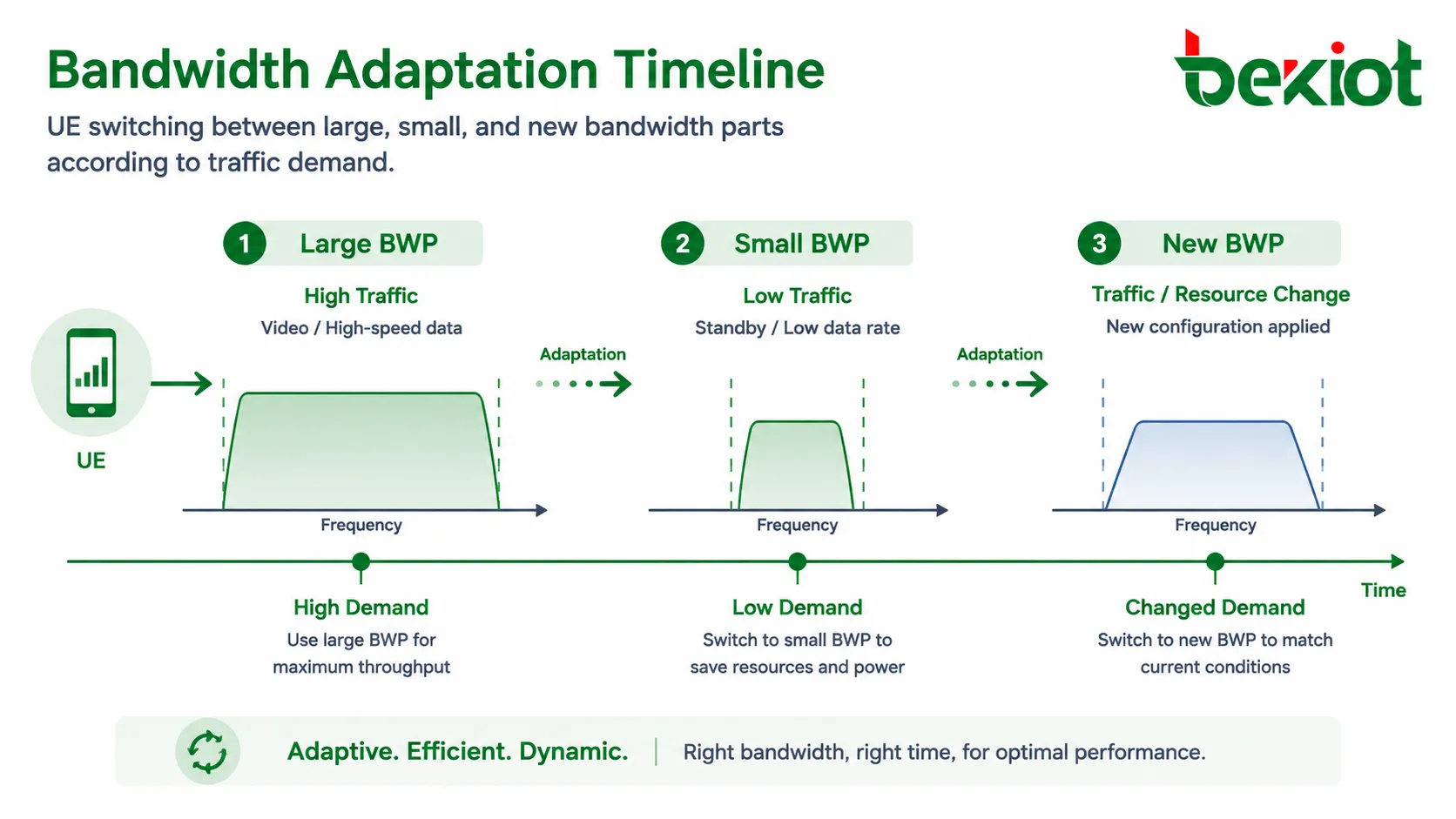
How Bandwidth Adaptation Works
After a UE accesses the network, multiple BWPs may be configured for it. The network can switch the UE between different BWPs according to service load, power-saving strategy, and available radio resources. This dynamic adjustment is often described as bandwidth adaptation.
When the UE has heavy traffic, such as high-speed data transmission, video uplink, or large-volume download, the network may activate a wider BWP. When the UE has lighter traffic, such as signaling, standby, small data transfer, or low-rate industrial telemetry, the network can move the UE to a narrower BWP to reduce unnecessary processing and energy consumption.
Bandwidth adaptation is also useful when a previously used frequency region becomes congested. If the resource area of one BWP is under pressure, the network may configure or activate another BWP so that the UE can continue service with better resource availability.
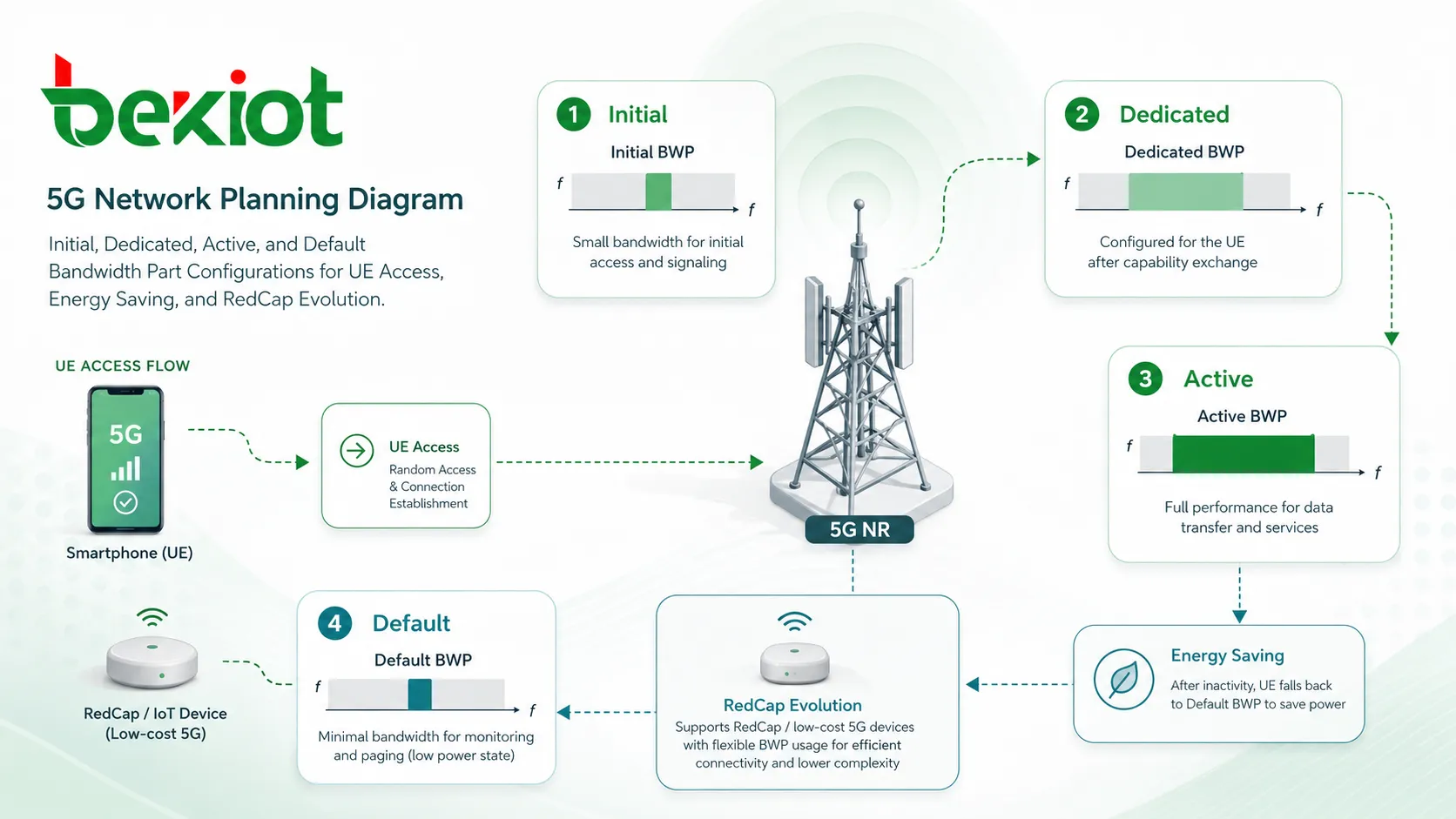
Four Common Configuration Types
In practical 5G NR operation, BWPs are not all used in the same way. The network may configure different types of BWPs depending on access stage, RRC state, service demand, and inactivity behavior. Understanding these types is important for radio planning, feature verification, and network troubleshooting.
Initial Configuration
Initial BWP is used during the initial access procedure. It supports the transmission and reception of essential access-related messages. It can be divided into uplink initial BWP and downlink initial BWP.
In early access, the UE may use the initial BWP to receive RMSI and OSI, and to perform random access procedures. This configuration is related to the cell and provides a controlled entry point before the UE receives more dedicated configuration.
Dedicated Configuration
Dedicated BWP is configured when the UE is in RRC connected state. A UE can be configured with multiple dedicated BWPs. According to the protocol description, up to four BWPs may be configured for a UE, allowing the network to match different terminal capabilities and traffic requirements.
Typical bandwidth choices may include 20MHz, 60MHz, 80MHz, and 100MHz depending on frequency range, deployment strategy, and device support. For FR2 operation, current configuration is more limited, and one dedicated BWP may be configured, with bandwidth examples such as 100MHz or 200MHz.
Active Configuration
Active BWP refers to the BWP currently used by the UE in RRC connected state. Although multiple BWPs may be configured, the UE can only activate one initial or dedicated BWP at the same time.
The UE sends and receives information within the active BWP range. This rule is important because it controls UE monitoring behavior, reduces processing burden, and allows the network to coordinate scheduling more efficiently.
Default Configuration
Default BWP is the bandwidth part that the UE returns to when the BWP inactivity timer expires. If a default BWP is configured, the UE falls back to that configured bandwidth part after inactivity. If no default BWP is configured, the initial BWP may be used as the fallback configuration.
This mechanism prevents a UE from remaining in a wide active bandwidth when there is no meaningful traffic. It supports power-saving behavior while keeping the device ready for future scheduling.
Technical Benefits for Devices and Networks
The first benefit of BWP is lower terminal complexity. Since a UE does not always need to support the full carrier bandwidth, lower-cost devices can be designed with reduced RF and baseband requirements. This helps expand the 5G device ecosystem and supports more diversified terminal categories.
The second benefit is power saving. When service traffic is small, the UE can operate in a narrower bandwidth region. This reduces unnecessary wideband monitoring and processing, which is especially valuable for battery-powered devices, industrial sensors, lightweight terminals, and future reduced-capability applications.
The third benefit is forward compatibility. When 5G introduces new features or new service mechanisms, the network can place certain capabilities on specific BWPs without disrupting all existing bandwidth configurations. This makes it easier to support technology evolution while maintaining compatibility with earlier devices.
Where Multi-BWP Design Is Useful
Multi-BWP design is valuable when different terminals and services need to share the same 5G cell. A terminal that supports only a smaller bandwidth can still access a larger-bandwidth network by using a BWP that matches its capability.
It also supports dynamic energy saving. The UE may switch between large and small bandwidth regions according to traffic demand. For high-throughput service, a wider BWP can be activated. For low-rate service or inactive periods, a narrower BWP can reduce power consumption.
Different services may also be carried on different BWPs. For example, one BWP may be planned for normal data traffic, another for lower-power operation, and another for a new service feature or special scheduling strategy. This gives radio engineers a more flexible tool for service separation and resource management.
Field Planning Examples
BWP configuration depends on total cell bandwidth, UE capability, service demand, and deployment strategy. In field network planning, TNR and FNR scenarios may use different multi-BWP combinations to match actual spectrum and device requirements.
| Network Scenario | Cell Bandwidth | Example Multi-BWP Configuration | Planning Purpose |
|---|---|---|---|
| TNR cell | 100MHz | 20MHz initial BWP + 100MHz dedicated BWP + 20MHz dedicated BWP | Supports initial access, high-throughput service, and low-bandwidth operation |
| TNR cell | 100MHz | 100MHz initial BWP + 100MHz dedicated BWP + 20MHz dedicated BWP | Provides wide initial access while keeping a narrow option for power saving |
| FNR cell | 40MHz | 20MHz initial BWP + 40MHz dedicated BWP + 20MHz dedicated BWP | Balances mid-bandwidth access, full-cell service, and reduced-bandwidth operation |
| FNR cell | 30MHz | 30MHz initial BWP + 30MHz dedicated BWP + 20MHz dedicated BWP | Matches smaller carrier bandwidth while keeping a narrower service option |
Relationship with RedCap and Future Devices
BWP is also important for the evolution of reduced-capability devices. RedCap terminals are designed for scenarios that do not require full enhanced mobile broadband capability. These devices may focus on lower cost, lower power consumption, and sufficient performance for industrial monitoring, wearables, video sensors, smart city nodes, and enterprise IoT applications.
Because BWP allows a terminal to operate within a smaller bandwidth region inside a larger 5G carrier, it provides a useful foundation for device categories that do not need full-bandwidth operation. This makes BWP an important part of long-term 5G network flexibility.
Deployment Considerations for Engineers
When designing BWP strategy, engineers should consider UE capability, service mix, coverage requirements, scheduling behavior, and energy-saving targets. A wider BWP is not always better. It may improve throughput potential, but it may also increase UE processing load and power consumption.
A narrower BWP is useful for low-rate traffic, but it may not be suitable for services that require high data rates or low scheduling delay. Therefore, BWP planning should be based on real service models rather than a single fixed bandwidth rule.
The inactivity timer should also be planned carefully. If the timer is too short, the UE may switch back too frequently and increase control overhead. If the timer is too long, the UE may remain in a wider BWP longer than necessary, reducing the power-saving benefit.
Conclusion
Bandwidth Part is a key 5G NR mechanism for dividing and managing carrier bandwidth. It allows the base station to configure a continuous bandwidth region for a UE, instead of forcing every device to support the full carrier bandwidth. This helps reduce UE cost, lower power consumption, improve service flexibility, and support future 5G evolution.
The value of BWP is not only in bandwidth reduction. Its real strength is adaptive control. A UE can use a larger bandwidth when traffic demand is high, move to a smaller bandwidth when demand is low, and operate within a suitable resource range according to terminal capability and network strategy. For 5G network planning, BWP is one of the practical tools that connects radio efficiency, device diversity, and long-term service evolution.
FAQ
Is BWP the same as carrier bandwidth?
No. Carrier bandwidth is the total bandwidth configured for the cell, while BWP is a smaller continuous bandwidth region inside that carrier. A UE may operate within a BWP without using the entire carrier bandwidth.
Can different users in the same cell use different BWPs?
Yes. Different UEs can be configured with different BWPs according to device capability, service demand, and radio resource planning. This is one of the reasons BWP is useful in mixed-device 5G networks.
Does BWP switching interrupt user service?
BWP switching is designed to be controlled by the network and coordinated through protocol procedures. In a well-planned network, switching should support service continuity, although poor configuration may affect user experience or scheduling efficiency.
Why is BWP important for low-cost 5G terminals?
Low-cost terminals may not need full carrier bandwidth. BWP allows these devices to operate within a smaller bandwidth range, reducing hardware requirements while still allowing access to a larger 5G network.
What should be tested when verifying BWP performance?
Engineers should test access behavior, active BWP switching, fallback after inactivity timer expiry, throughput under different BWP sizes, power consumption, and compatibility with different UE categories.