Relay output is an electrical control interface that allows one device or system to switch another circuit on or off through a relay contact. It is commonly used in alarm systems, access control, industrial automation, communication devices, building management systems, security panels, intercoms, fire alarm interfaces, control rooms, and IoT equipment.
Instead of directly powering every connected device, a relay output provides a controlled switching point. When the system detects an event, receives a command, or reaches a programmed condition, the relay changes state and can activate an external device such as a siren, beacon, electric lock, gate controller, warning light, pump input, PLC signal, or alarm panel input.
From Electrical Signal to Field Action
In many systems, software decisions need to create physical actions. A security platform may need to unlock a door. A communication terminal may need to activate a beacon. A sensor may need to trigger an alarm panel. A building system may need to start a fan or notify a controller.
Relay output makes this connection possible. The control device sends a small internal signal to the relay. The relay then opens or closes an external circuit. This allows a low-power electronic system to control a separate electrical circuit without directly sharing the same power path.
This separation is one reason relays are widely used. They help connect devices that may use different voltages, different power sources, or different system roles, while keeping the control side and load side more clearly separated.
How the Switching Interface Works
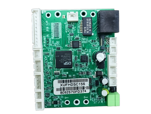
Relay Coil or Internal Drive
A traditional electromechanical relay uses a coil. When the control circuit energizes the coil, it creates a magnetic field that moves internal contacts. In many modern devices, the user may not see the coil directly because it is built into the product circuit.
Some systems use solid-state relay outputs instead of mechanical relays. A solid-state design performs switching electronically, with no moving contacts. Each type has advantages depending on load type, switching frequency, service life, noise, and isolation requirements.
Contact State Change
The output contact changes state when activated. It may close a circuit, open a circuit, or switch between two paths. This contact behavior is what allows the controlled device to respond.
For example, when a door intercom approves access, a relay contact may close for three seconds to tell the door controller to unlock. When a sensor detects a fault, the relay may open a normally closed circuit to indicate an alarm condition.
External Power Path
A relay output often does not provide power by itself. It may simply act like a switch. The external device may need its own power supply, and the relay only controls whether that power path is connected.
This is an important installation detail. If a technician expects the relay to output voltage but the device only provides a dry contact, the connected equipment may not work until an external power source is added correctly.
Electrical Isolation
One practical benefit of relay switching is isolation. The device controlling the relay can remain electrically separated from the circuit being switched. This helps protect sensitive electronics from certain external electrical conditions.
Isolation does not remove the need for proper wiring, surge protection, grounding, fusing, or load rating. It simply gives designers a useful boundary between control logic and field wiring.
Contact Types and Their Meaning
Normally Open
A normally open contact stays open when the relay is not activated. When the relay activates, the contact closes and completes the circuit. This is commonly used when an external device should turn on only during an event.
Typical examples include activating a strobe light, triggering a chime, sending a door release pulse, or starting an alarm input only when a condition occurs.
Normally Closed
A normally closed contact stays closed when the relay is not activated. When the relay activates, the contact opens. This is useful when the system needs to detect interruption, fault, tamper, or fail-safe behavior.
For example, some alarm circuits are designed so that a broken wire or open contact creates an alarm condition. This can be safer than relying only on a closing contact.
Common Terminal
The common terminal is the shared point used by relay contacts. In an SPDT relay, the common terminal can switch between normally open and normally closed terminals.
Understanding the common terminal is essential during installation. Incorrect wiring can make the controlled device behave in reverse or fail to activate.
Dry Contact and Wet Contact
A dry contact is a relay contact that does not provide voltage. It only opens or closes a circuit. A wet contact provides or switches a voltage from the output device or connected circuit, depending on the design.
Dry contacts are widely used because they offer flexibility. They can connect to many control systems as long as the voltage and current ratings are respected.
Core Features That Matter in Selection
Contact Rating
The contact rating defines how much voltage and current the relay can switch safely. This rating must match the connected load. A relay designed for low-current signaling should not be used to switch a high-power motor directly.
Ratings may differ for AC and DC loads. DC loads can be harder to interrupt because the arc may not extinguish as easily as in AC circuits. Always check the load type before wiring.
Trigger Mode
Relay output can be triggered by different events. A device may activate the relay when a call is received, an alarm is detected, a button is pressed, a door is opened, a sensor threshold is reached, or a software command is executed.
Some systems allow flexible programming. The relay may pulse for a defined time, remain active until reset, follow a schedule, respond to priority events, or activate only under combined conditions.
Pulse Duration
Many access control and signaling applications require a timed pulse. For example, an electric lock may need a three-second unlock signal, while a gate controller may need a short dry contact closure.
Adjustable pulse duration makes deployment easier because different external devices may require different trigger times.
Manual and Automatic Control
A relay output may be controlled automatically by system logic or manually by an operator. Manual control is useful for testing, door release, emergency operation, maintenance checks, or temporary override.
Automatic control is useful when the relay must respond quickly to events without human delay, such as alarm triggering, sensor response, and system interlock actions.
Status Feedback
Basic relay outputs only switch a circuit. More advanced systems may also provide feedback about relay state, external device response, input confirmation, or fault condition.
Feedback is valuable because activating a relay does not always prove that the external device performed the expected action. A door may fail to unlock, a beacon may lose power, or a siren may be disconnected.
Relay output is most useful when it is treated as a controlled interface, not just as a simple wire connection. Ratings, contact type, timing, and external power design all matter.
Typical Wiring Logic
Relay output wiring depends on whether the connected device expects a dry contact, a voltage trigger, a normally open input, or a normally closed input. The installer must read both the relay device manual and the external equipment wiring requirements.
For a dry contact trigger, the relay usually connects two input terminals on the external system. When the relay closes, the external system detects the closed circuit. For a powered load, the relay may be wired in series with a power supply and the load, acting like an on/off switch.
When controlling inductive loads such as locks, relays, motors, or solenoids, protection components may be required to reduce voltage spikes. Without protection, relay contacts may wear faster and electronic circuits may be damaged.
| Use Case | Common Contact Behavior | Installation Focus |
|---|---|---|
| Door Release | Normally open contact closes for a short pulse. | Correct lock power, pulse duration, and fail-safe or fail-secure design. |
| Alarm Panel Trigger | Normally open or normally closed depending on panel input type. | Input supervision, wire monitoring, and alarm reset behavior. |
| Beacon or Strobe | Contact closes to power or trigger visual alert. | Load current, external power supply, and weatherproof wiring. |
| Industrial Controller Input | Dry contact sends a status or event signal. | Voltage compatibility, isolation, and PLC input logic. |
| Siren Activation | Relay closes to start audio warning or alarm controller input. | Priority logic, power capacity, and manual reset requirement. |
Where This Interface Is Used
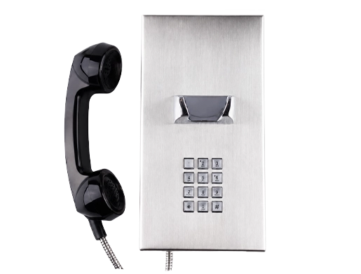
Access Control and Door Entry
Door entry systems often use relay outputs to unlock electric strikes, magnetic locks, gate operators, turnstiles, or barrier arms. When an authorized user is verified, the system activates the relay for a defined period.
Access control wiring must consider safety. Fail-safe locks, fail-secure locks, fire alarm release, emergency exit requirements, and local regulations may affect how the relay is used.
Security and Alarm Systems
Security devices use relay outputs to trigger alarm panels, sirens, strobes, dialers, monitoring systems, or CCTV actions. A motion detector, panic button, door sensor, or tamper alarm may activate a relay output when an event occurs.
In security applications, normally closed circuits may be preferred for some functions because they can detect wire cuts or disconnection more easily than basic normally open wiring.
Industrial Automation
Industrial systems use relays to interface between sensors, PLCs, machines, alarms, control panels, and field devices. A relay output may signal machine status, stop a process, activate a warning light, or notify a supervisory control system.
Industrial environments require careful attention to voltage levels, electrical noise, vibration, cable routing, and protective components. Relay outputs should not be overloaded or used beyond their rated capacity.
Building Management
Building systems may use relay outputs to control fans, dampers, lighting interfaces, elevators, HVAC alarms, emergency panels, or facility signals. The relay may respond to schedules, alarms, occupancy sensors, or system commands.
Because building systems often involve multiple contractors, wiring documentation and labeling are important. A poorly labeled relay can be difficult to troubleshoot later.
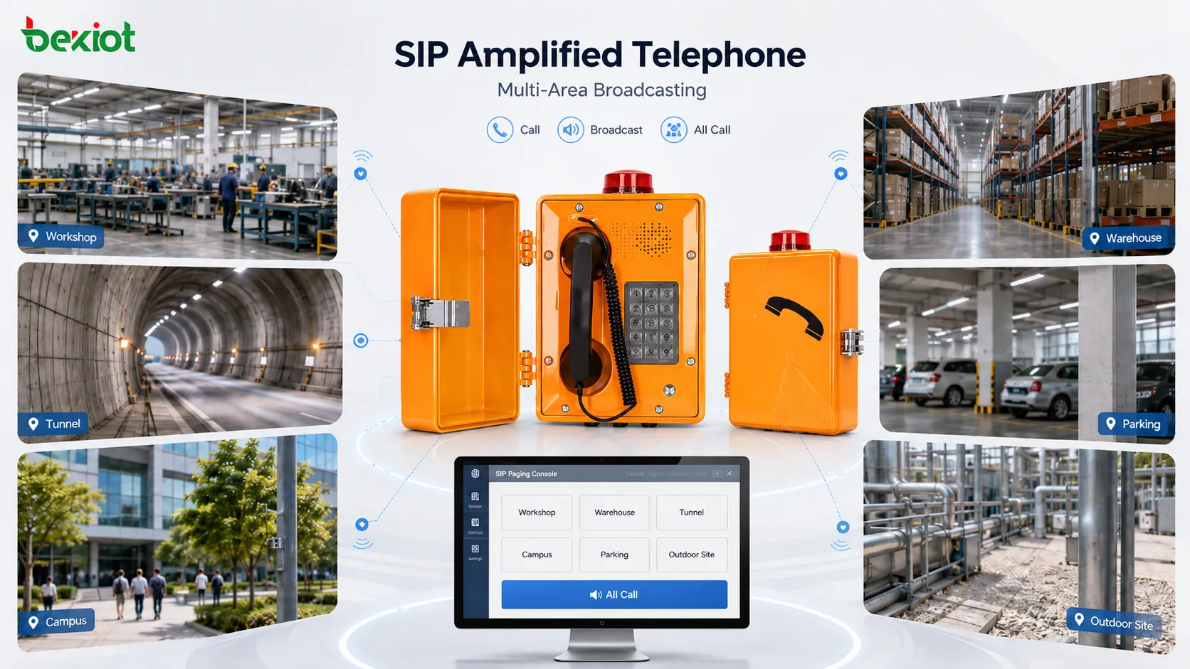
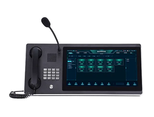
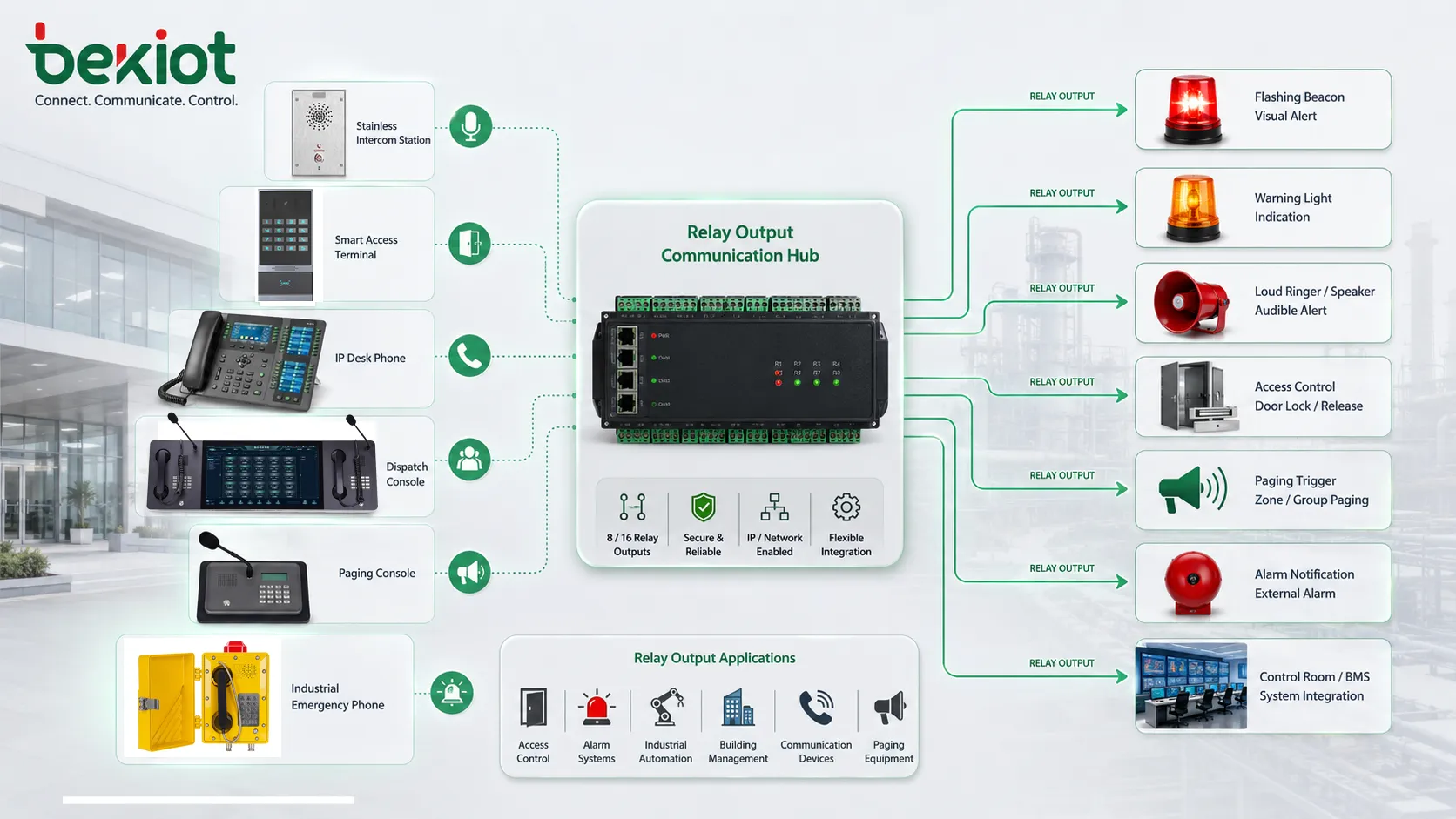
Communication and Paging Equipment
Communication devices may use relay outputs to activate external bells, visual indicators, door locks, loud ringers, alarm beacons, recording triggers, or paging system inputs. This is common in intercoms, IP phones, emergency call stations, dispatch consoles, and public address systems.
For example, an incoming call may trigger a flashing light in a noisy workshop, or an emergency button may close a relay to activate a local siren and notify a control room.
Benefits for System Integration
Simple Interconnection
Relay outputs are easy to understand and widely supported. Many devices can accept a contact closure as a trigger. This makes relays useful for integrating systems from different manufacturers.
Even when software protocols are incompatible, a relay output can provide a basic physical signal between devices.
Electrical Separation
Relay contacts can separate the control circuit from the external circuit. This helps reduce direct electrical dependency between systems, especially when devices use different power sources or signaling methods.
Isolation is valuable, but it should not be confused with complete protection. Surge protection, correct grounding, cable shielding, and proper installation are still important.
Flexible Control Logic
Relay outputs can be tied to many different events. This makes them useful for both routine automation and emergency actions. A single relay may be configured to follow a schedule, respond to an input, activate on call arrival, or trigger after a sensor threshold.
Flexibility is especially useful in facilities where communication, security, and automation systems need to work together.
Reliable Field Operation
Mechanical relays are familiar, proven, and easy to test. Technicians can often verify relay behavior with a multimeter, continuity tester, or simple load circuit.
This practical serviceability makes relays attractive in field installations where troubleshooting must be fast and clear.
Design Considerations Before Deployment
Load Type
The connected load may be resistive, inductive, capacitive, or electronic. A lamp behaves differently from a lock coil, motor, relay coil, or PLC input. Load type affects contact wear and protection needs.
Inductive loads should often use suppression components such as flyback diodes, MOVs, snubbers, or manufacturer-recommended protection devices.
Voltage and Current
The relay contact rating must be higher than the actual load requirement. Do not assume that a relay can control any device just because the terminals fit.
For higher-power equipment, the relay output may need to drive an intermediate contactor or control relay rather than the load directly.
Fail-Safe Behavior
System designers should decide what happens during power loss, cable failure, device fault, or relay failure. In safety and access control systems, this decision is important.
A door lock, alarm output, or machine interlock may require a different fail-safe strategy depending on life safety, security, and operational requirements.
Wiring Distance
Long cable runs can introduce voltage drop, electrical noise, and troubleshooting difficulty. Relay wiring should be routed and protected according to the site environment.
For long-distance signaling, shielded cable, surge protection, proper grounding, or conversion to a supervised input may be needed.
Environmental Protection
Relays and connected terminals may be installed in outdoor, dusty, humid, or industrial environments. Enclosures, cable glands, terminal blocks, and connectors should match the site conditions.
Moisture or corrosion at relay terminals can create intermittent faults that are difficult to diagnose.
The most common relay output problems are not caused by the relay concept itself, but by mismatched load ratings, unclear wiring logic, or missing protection for real field conditions.
Common Problems and Troubleshooting
Connected Device Does Not Activate
If the external device does not respond, check whether the relay is actually changing state, whether the external device has power, and whether the wiring matches normally open or normally closed logic.
Also confirm whether the external device expects a dry contact or a voltage signal. This is a frequent installation mismatch.
Output Works in Reverse
If a device activates when it should be off, the installer may have used the normally closed terminal instead of the normally open terminal, or the external controller may be configured with opposite input logic.
Review the wiring diagram and input configuration before changing hardware.
Relay Contacts Wear Out
Contacts can wear from high current, frequent switching, inductive loads, arcing, or unsuitable voltage conditions. If the relay switches often or controls a demanding load, contact life should be considered during design.
Using a relay within its rating and adding proper suppression can extend service life.
Intermittent Activation
Intermittent problems may come from loose terminals, cable movement, corrosion, vibration, poor grounding, damaged contacts, or unstable external power. These faults may appear only under real operating conditions.
Technicians should inspect wiring physically, not only check software settings.
Maintenance and Testing Tips
Relay outputs should be tested during commissioning and after major system changes. A test should confirm activation logic, contact type, pulse duration, external device response, and reset behavior.
Terminals should be inspected for loose screws, corrosion, overheating marks, broken conductors, damaged insulation, and poor strain relief. In industrial environments, vibration can loosen connections over time.
For critical systems, maintenance records should include relay purpose, connected device, wiring diagram, contact type, voltage, current, fuse rating, and test result. Clear documentation makes future troubleshooting much easier.
Choosing the Right Output Design
The right design depends on what the relay needs to control. A door release may need a timed dry contact. A siren may need a contact rated for a powered circuit. A PLC input may need isolated low-current signaling. A safety device may require supervised or fail-safe wiring.
When in doubt, design the relay output as an interface rather than the main power path. For larger loads, use the relay to drive an intermediate device designed for the required power level.
Good design also includes protection. Fuses, suppression components, proper cable routing, environmental sealing, and clear labeling can prevent many field failures.
FAQ
Can a relay output directly power an external device?
Sometimes, but not always. Many relay outputs are dry contacts and do not supply voltage. The external device may need a separate power supply, with the relay acting only as the switch.
How can I test whether a relay contact is working?
A technician can usually test continuity between the common and output terminals while activating the relay. Testing should be done safely and according to the device manual, especially when higher voltages are involved.
Why is a protection diode used with some locks or coils?
Coils can create voltage spikes when switched off. A protection diode or other suppression component helps reduce that spike and protects relay contacts and electronic circuits.
What is the difference between relay output and open collector output?
A relay output uses a contact-style switch and often provides isolation. An open collector output is a transistor-based electronic output that usually switches a low-voltage DC signal and requires correct polarity and pull-up design.
When should an intermediate relay or contactor be used?
Use an intermediate relay or contactor when the load current, voltage, inrush current, or switching type exceeds the small relay output rating of the control device.