In engineering procurement, product selection, industrial equipment design, communication system planning, and long-term maintenance management, MTBF and protection level are often used together to judge whether a device is reliable enough for the intended environment. A high MTBF value may suggest lower expected failure frequency, while a suitable protection level may show that the enclosure or product structure can resist dust, water, impact, corrosion, electrical stress, or other site conditions. However, these two indicators are frequently misunderstood when they are treated as simple marketing numbers instead of engineering judgments.
MTBF is determined through reliability assumptions, calculation methods, component data, operating conditions, and failure definitions. Protection level is judged through environmental tests, enclosure tests, mechanical tests, certification requirements, and application matching. A product with an impressive MTBF number may still fail early if it is installed in an unsuitable environment. A product with a high protection rating may still be unreliable if internal components, thermal design, power quality, or maintenance practices are weak. The two indicators should be read together, but they should not be confused with each other.
Reliability targets start with the failure boundary
Before MTBF can be calculated or judged, the project team must define what counts as a failure. This step is often more important than the formula itself. A device may stop completely, restart unexpectedly, lose communication, produce incorrect output, display wrong status, fail to meet timing requirements, or require manual reset. Some of these conditions may be counted as failures in one project but treated as temporary anomalies in another. Without a clear failure boundary, the MTBF value becomes difficult to interpret.
For repairable equipment, MTBF usually refers to the average operating time between failures that require repair or corrective action. If a system operates for a long period and experiences several valid failures, MTBF can be calculated by dividing total operating time by the number of failures. In reliability prediction, MTBF may also be estimated from failure-rate models before enough field data exists. These two approaches can produce different values because one is based on prediction and the other is based on observed operation.
The failure boundary should match the purpose of the product. For a monitoring terminal, screen failure, communication loss, or power supply failure may be counted. For a network device, packet forwarding failure, port failure, reboot, configuration corruption, or management loss may be counted. For a safety-related device, failure to alarm, failure to communicate, wrong indication, or delayed response may be more important than minor cosmetic problems.
The project should also define what is not counted as a product failure. External power loss, incorrect installation, cable damage, wrong configuration, unauthorized modification, lightning without protection, water entry through improper cable glands, or operation outside rated conditions may be excluded from product MTBF calculation, although they still affect real project availability. This distinction prevents MTBF from being blamed for every site problem while also reminding engineers that site reliability includes more than the product itself.
The calculation must match the equipment type
MTBF is mainly meaningful for repairable systems or equipment that can return to service after repair. Servers, communication devices, industrial controllers, power modules, monitoring terminals, network switches, gateways, and many field devices can be repaired, replaced, or restored. In these cases, the average time between repair-relevant failures helps estimate service continuity and maintenance burden.
For non-repairable components, MTTF, or mean time to failure, may be more appropriate. A small electronic component, sealed module, lamp, sensor element, or single-use device may not be repaired after failure. Using MTBF carelessly for non-repairable items can create confusion. The correct reliability indicator depends on whether the item is repaired, replaced, restored, or discarded after failure.
MTBF should also be separated from service life. A product may have an MTBF value much longer than its warranty period or expected service life because MTBF is a statistical reliability indicator, not a promise that one unit will run for that exact number of hours. For example, a product with a high predicted MTBF can still fail early due to manufacturing defects, transportation damage, unsuitable installation, overheating, surge, moisture, or component variation.
Another common confusion is between MTBF and availability. Availability depends not only on how often failures occur, but also on how quickly the system can be restored. A device with moderate MTBF and very short repair time may provide better practical availability than a device with higher MTBF but difficult maintenance. This is why MTTR, spare parts, modular replacement, remote diagnosis, and maintenance access should be reviewed together with MTBF.
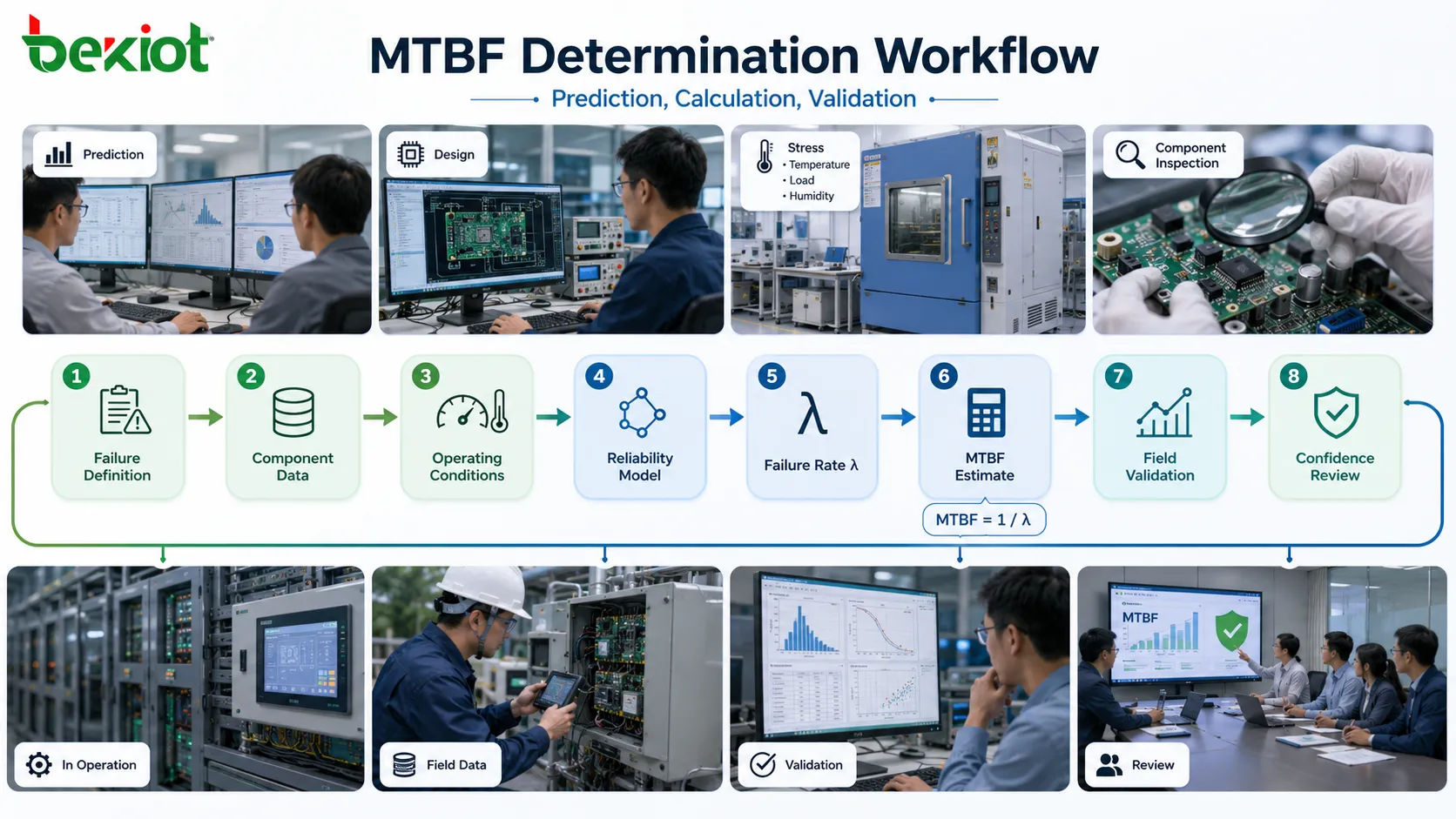
Prediction methods use models before field data is mature
During product design or early procurement, complete field data may not yet exist. In this stage, MTBF is often estimated through reliability prediction methods. These methods use component failure rates, stress factors, environmental conditions, temperature, electrical load, quality level, operating profile, and sometimes application category to estimate the expected failure rate of the whole product.
Common reliability prediction approaches may use handbooks, industry procedures, manufacturer data, field databases, or internal reliability models. The selected method should be appropriate for the product category and industry. Electronic equipment, mechanical systems, power devices, telecom equipment, industrial controllers, and safety systems may require different assumptions and data sources. A prediction method designed for one environment may not accurately reflect another.
The basic logic is usually to estimate the failure rate of each component or module, adjust it according to operating stress, then combine the values into a system-level failure rate. If the system failure rate is expressed as lambda, MTBF is often estimated as the reciprocal of the failure rate under the assumptions of a constant failure-rate region. This calculation depends heavily on the quality of the input data.
Prediction is useful because it helps engineers compare design options before long-term operation records are available. It can show which components contribute most to expected failures, whether temperature reduction improves reliability, whether derating is needed, whether a fan or power supply is a weak point, and whether the design target is realistic. However, prediction should be treated as an engineering estimate, not as an absolute guarantee.
When reporting predicted MTBF, the method should be named clearly. A value calculated using one prediction procedure cannot always be compared directly with a value calculated using another procedure. Different models may use different component classifications, environmental assumptions, quality factors, stress models, and confidence approaches. Without the method, the number alone is incomplete.
Observed data gives reality but needs enough scale
Field data is valuable because it reflects actual operating conditions. If a large number of units have been operating for a long time and valid failures are recorded accurately, the observed MTBF can be more meaningful than early prediction. It shows how the equipment performs under real temperature, humidity, power quality, user behavior, workload, maintenance, and installation conditions.
However, field data must be handled carefully. A small sample can be misleading. If only a few units have operated for a short time, the absence of failures does not prove extremely high reliability. It may simply mean that the observation period is too short. Reliability statistics need enough operating hours, enough installed units, and clear failure records to support a credible conclusion.
The source of field data also matters. Data from controlled laboratory operation may not match data from outdoor industrial sites. Data from one region may not match another region with different climate, power quality, maintenance skill, or usage intensity. Data from a mature product may not apply to a newly redesigned version. Field MTBF should be tied to a known product version, installation condition, and operating profile.
Failure records should be classified. Some failures may be component failures. Some may be installation errors. Some may be damage caused by misuse. Some may be firmware issues. Some may be external environmental events. If all events are counted together without classification, the MTBF may unfairly represent product reliability or hide site-related problems. If too many events are excluded casually, the value may become too optimistic.
Good field reliability analysis usually combines failure logs, repair records, returned material analysis, root cause classification, environmental notes, firmware version, production batch, and operating time. The goal is not only to calculate a number but also to understand why failures occur and how design, installation, or maintenance can be improved.
Operating conditions decide whether the number is meaningful
MTBF values should always be interpreted together with operating conditions. Temperature is one of the most important factors for electronic equipment. Higher operating temperature can accelerate component aging, reduce capacitor life, affect power modules, increase solder stress, and shorten the life of fans or batteries. A product tested or predicted at a comfortable indoor temperature may not perform the same in a hot cabinet or outdoor enclosure.
Electrical stress also matters. Components operated near their maximum voltage, current, power, or thermal limits may fail sooner than components operated with proper derating. Power surges, unstable input voltage, poor grounding, and electromagnetic interference can all affect reliability. MTBF should not be evaluated without considering the real electrical environment.
Mechanical and environmental stress can also change reliability. Vibration, shock, dust, moisture, salt spray, chemical vapor, UV exposure, repeated button operation, cable pulling, and connector corrosion may create failures that are not fully represented by a general electronic reliability calculation. For field equipment, the installation environment may be just as important as the circuit design.
Duty cycle should be considered. A device operating continuously at high load may not have the same failure rate as one used intermittently. A paging amplifier, industrial phone, gateway, display terminal, or network device may experience different thermal and electrical stress depending on how often it transmits, rings, displays, records, drives audio, or handles traffic. MTBF assumptions should reflect the mission profile rather than an abstract ideal condition.
This is why a responsible MTBF statement should include or reference the calculation conditions. A bare statement such as “MTBF 100,000 hours” is less useful than a statement that explains the standard, environment, temperature, duty cycle, failure definition, and data source. The context turns the number into an engineering indicator.
Component data and derating shape the result
Many MTBF predictions begin at component level. Resistors, capacitors, integrated circuits, transistors, diodes, connectors, relays, switches, fans, displays, batteries, power supplies, and other parts may each contribute to the total failure rate. Some components usually contribute more risk than others depending on stress, temperature, quality, and application.
Electrolytic capacitors, fans, batteries, relays, connectors, and mechanical switches often deserve special attention because they may have wear-out mechanisms, limited lifetime, or higher sensitivity to environmental conditions. Even if the overall predicted MTBF looks acceptable, one weak component can dominate field failures. Reliability analysis should therefore identify high-contribution parts rather than only report the final number.
Derating is a common reliability design method. Instead of operating components close to their maximum ratings, engineers select parts with voltage, current, temperature, or power margins. For example, a capacitor may be selected with voltage rating higher than the actual operating voltage, or a power component may be sized to reduce thermal stress. Proper derating can improve long-term reliability.
Component quality and supplier control also matter. Two components with the same nominal rating may not perform equally under industrial conditions. Reliability depends on manufacturing quality, process control, material stability, supplier consistency, and incoming inspection. If component data is uncertain, the MTBF prediction may be uncertain as well.
For complex products, module-level design also affects reliability. Heat layout, PCB spacing, conformal coating, connector strain relief, sealing, grounding, firmware stability, protection circuits, and mechanical support all influence real failures. MTBF is not only a parts list calculation; it reflects how parts are used in a complete design.
Confidence level changes how results should be read
Reliability numbers should be read with statistical caution. When MTBF is based on test or field data, confidence level is important. A claim based on limited data may have a wide uncertainty range. A higher confidence requirement usually needs more test time, more samples, or more observed operating hours. Without confidence information, a reliability statement may look more precise than it really is.
For example, if several units run for a short period without failure, the observed result may be encouraging but not enough to prove a very high MTBF with strong confidence. Zero failures does not mean infinite reliability. It means no failures were observed during the test conditions and duration. The statistical interpretation depends on the sample size and confidence method.
When failures occur during testing, the calculation should consider whether they are valid failures, early manufacturing defects, test setup problems, external faults, or design weaknesses. Removing failures from the calculation should be justified. Otherwise, the reported MTBF may become artificially high.
For procurement and project acceptance, it is useful to ask whether the MTBF value is predicted, tested, or field-observed. A predicted value supports design comparison. A tested value supports controlled verification. A field-observed value supports real-use confidence. These sources are not equivalent, and each has limitations.
Confidence also affects protection-level judgment. Passing one enclosure test under one condition does not mean the product is protected against every real-world hazard. Ratings should be read according to the exact test method, sample condition, mounting orientation, cable entry, gasket state, temperature, and intended use.
Standard selection depends on industry and purpose
The standard used to determine MTBF should be selected according to product type, industry expectation, customer requirement, data availability, and project risk. Military, aerospace, telecom, industrial automation, commercial electronics, transportation, medical, and utility applications may not use the same reliability prediction method. A standard familiar in one sector may be less suitable in another.
Some reliability prediction procedures are based on electronic component models. Some emphasize telecom equipment reliability. Some use reference conditions and stress conversion. Some allow field data or manufacturer data to be incorporated. Some are more appropriate during design, while others are used for contractual comparison or safety analysis. The project should state why a particular method is chosen.
If a customer specification names a required standard, the supplier should follow that method or clearly explain deviations. If no standard is specified, the engineering team should choose a method that matches the product and market. For example, electronic equipment may use electronic reliability prediction methods, while mechanical assemblies may need different failure data and test approaches.
Cross-comparison should be avoided unless the method is aligned. A product predicted at one MTBF using one standard may appear better or worse than another product predicted using another method. The difference may come from the calculation model rather than the actual design. Reliable comparison requires consistent assumptions.
In many projects, the best approach is layered. Early design uses prediction to identify weak points. Prototype stage uses testing to verify major risks. Production stage uses quality control and burn-in where applicable. Field stage uses real failure data to update the reliability understanding. MTBF becomes a continuous engineering tool rather than a one-time brochure number.
| Determination source | Main use | Strength | Limitation |
|---|---|---|---|
| Reliability prediction | Design-stage estimation and comparison | Helps identify high-risk components before field data exists | Depends heavily on assumptions, models, and input data quality |
| Laboratory test data | Verification under controlled conditions | Provides measured evidence under known stress or operation | May not represent all field environments or long-term use |
| Field operation data | Real-use reliability evaluation | Reflects actual installation, usage, and maintenance conditions | Needs large sample size, clear records, and failure classification |
| Supplier or component data | Part-level reliability input | Useful for design models and component comparison | May be based on different environments or test assumptions |
| Customer acceptance requirement | Contract and procurement compliance | Creates a common evaluation basis | Can be misleading if the chosen method does not fit the application |
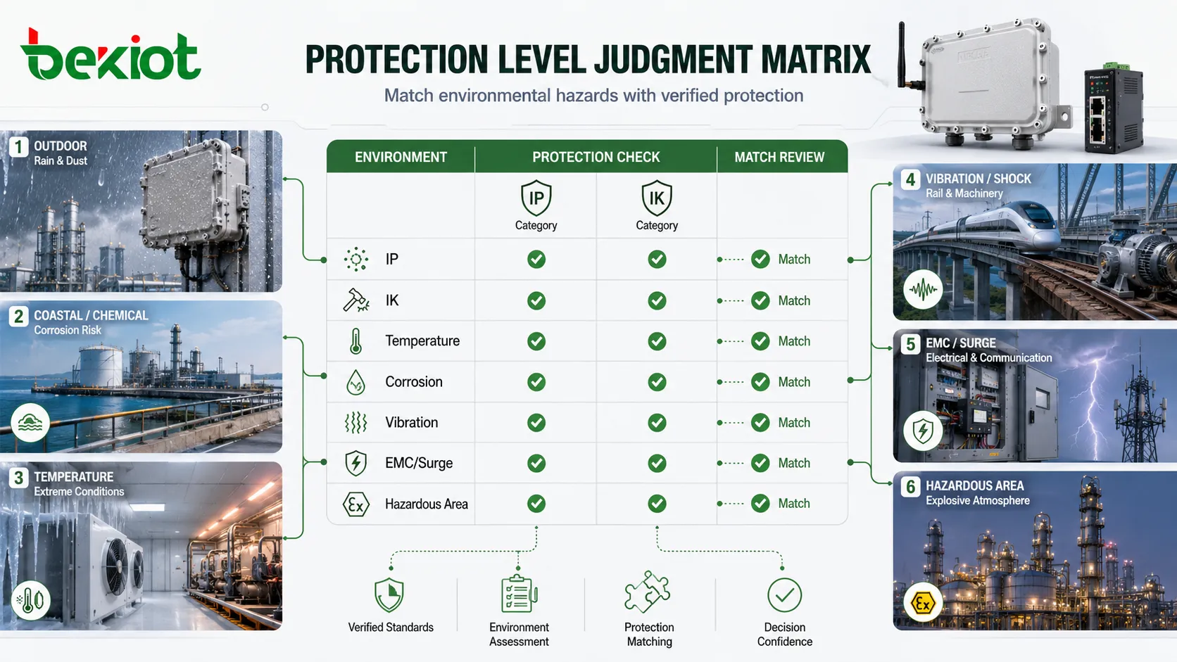
Protection level is judged by hazard matching
Protection level is different from MTBF. It does not describe how long a device will run between failures. It describes how well the device or enclosure resists specific external conditions. These conditions may include dust ingress, water ingress, mechanical impact, corrosion, flame exposure, electrical insulation stress, surge, electromagnetic interference, temperature, vibration, or hazardous-area requirements.
The first step in judging protection level is identifying the hazards in the application. A device installed in a clean office does not need the same protection as a device installed outdoors near a coastline. A control terminal inside a cabinet does not need the same impact resistance as a public emergency call point in a transport station. A device in a wash-down food processing area faces different risks from a device in a dry warehouse.
Protection judgment should therefore begin with the environment, not the product label. Is there dust? Is it conductive or non-conductive? Is water dripping, spraying, splashing, jetting, or immersing the device? Is the device exposed to direct sunlight, salt fog, chemicals, vibration, shock, public misuse, or temperature extremes? Is the device installed indoors, outdoors, under a roof, inside a cabinet, or directly on a machine?
Once the hazards are identified, the corresponding protection standards or test methods can be selected. In many electrical and electronic enclosure applications, IP ratings are used for solid and liquid ingress protection. IK ratings may be used for external mechanical impact resistance. Other environments may require corrosion tests, vibration tests, EMC tests, insulation tests, flame tests, or hazardous-area certification depending on product function and site risk.
A high rating in one category does not automatically mean high protection in another. A product may resist water but not strong impact. It may resist impact but not corrosion. It may be dust-tight but not suitable for explosive atmospheres. It may pass a laboratory ingress test but fail in a poorly installed field condition. Protection level must be judged category by category.
Ingress protection is only one part of protection
IP rating is one of the most familiar protection indicators. It usually describes the degree of protection provided by an enclosure against solid objects and water. The first digit relates to solid particle or access protection, while the second digit relates to liquid ingress protection. This makes IP codes useful for devices installed in dusty, wet, outdoor, wash-down, or public environments.
However, IP rating should not be simplified into “waterproof” or “dustproof” without reading the specific digits. Different water tests represent different conditions. Dripping water, spraying water, water jets, powerful jets, temporary immersion, and high-pressure high-temperature water exposure are not the same. A device suitable for rain may not be suitable for immersion. A device suitable for immersion may not automatically be suitable for high-pressure jet cleaning unless it has been tested for that condition.
The complete installation affects ingress protection. Cable glands, conduit entries, mounting orientation, gasket compression, front panel assembly, screw torque, maintenance access, and unused holes can all affect whether dust or water enters. A product may have a high enclosure rating in a test sample but lose protection if installed with poor cable sealing or damaged gaskets.
IP rating also does not judge internal reliability directly. A device may prevent water entry but still overheat if sealed too tightly. A sealed enclosure may trap condensation if temperature changes occur. A high IP enclosure may require thermal design, breathable membranes, drainage strategy, or conformal coating depending on the environment. Ingress protection should be balanced with heat and moisture management.
For procurement, the expected water and dust conditions should be described in practical terms. Instead of only asking for “high IP,” the project should state whether the device will face indoor dust, outdoor rain, hose cleaning, temporary flooding, salt mist, wash-down cleaning, or dust-laden air. The rating should match the real exposure.
Impact resistance and mechanical protection need separate judgment
Mechanical protection is often judged separately from ingress protection. A device may be installed in a place where it can be hit by tools, carts, luggage, vehicles, falling objects, public misuse, or repeated operation. In such cases, impact resistance becomes important. IK rating is commonly used to classify enclosure resistance to external mechanical impact according to defined test energy levels.
Impact resistance should be matched to the installation location. A device installed in a quiet office corridor may not need the same impact level as a device installed at a public platform, outdoor gate, warehouse dock, school corridor, parking area, or industrial passage. High traffic and public access usually increase mechanical risk.
The test condition matters. Impact tests are performed under defined methods, mounting conditions, impact energy, and impact locations. A rating does not mean the product can survive any possible strike from any direction. A product may resist a standard test impact but still be damaged by a sharp object, repeated abuse, vehicle collision, or impact on a vulnerable accessory such as a cable connector, screen, handset, or button.
Mechanical protection also includes mounting strength. A strong enclosure can fail in the field if it is fixed to a weak wall, thin sheet, loose bracket, or poor anchor. The whole installation should resist expected forces. Screws, brackets, back boxes, gaskets, hinges, locks, and front panels should be considered together.
For public and industrial devices, impact resistance should be combined with serviceability. A device that resists impact but is difficult to repair may still create long downtime. Replaceable front panels, protected screens, durable buttons, and accessible mounting hardware can improve lifecycle value.
Environmental protection must reflect real exposure
Beyond IP and IK, many products require additional environmental judgment. Temperature range is critical. A device installed outdoors, inside a sealed cabinet, near heat-generating equipment, or in a cold storage area may face temperatures beyond normal indoor conditions. Components, displays, batteries, gaskets, plastics, cables, and adhesives may all behave differently at temperature extremes.
Corrosion is another major factor. Coastal areas, chemical plants, wastewater facilities, marine environments, food processing areas, fertilizer plants, and industrial outdoor sites may expose equipment to salt, chemicals, moisture, or corrosive gases. A product that works well indoors may degrade quickly if the enclosure material, coating, screws, connectors, and cable entries are not suitable for corrosion exposure.
Vibration and shock should be judged for equipment installed on machines, vehicles, bridges, platforms, compressors, pumps, rotating equipment, rail environments, or heavy industrial structures. Vibration can loosen connectors, fatigue solder joints, damage displays, weaken screws, and affect relays or mechanical switches. Protection level in such cases may require vibration testing or special mounting methods.
EMC and surge protection are also important for electrical and communication devices. A product may be physically protected against dust and water but still fail due to lightning surge, electrostatic discharge, switching transients, radio interference, poor grounding, or cable-induced noise. Protection level should therefore include electrical immunity where relevant.
Hazardous-area protection is a separate category. If equipment is used in potentially explosive atmospheres, ordinary IP or IK ratings are not enough. The device must be selected according to the hazardous-area classification, certification, temperature class, gas or dust group, installation method, and maintenance rules. This should always be verified through applicable certificates and project requirements.
Test reports matter more than vague descriptions
Terms such as rugged, waterproof, weatherproof, industrial grade, heavy duty, outdoor rated, shock resistant, and high reliability are not enough for engineering judgment. They may describe intention, but they do not replace test evidence. Protection level should be supported by recognized test methods, clear rating codes, test reports, certificates, or technical specifications.
A useful test report should identify the tested product model, sample condition, test standard, test level, test method, test duration, mounting orientation, cable entry condition, acceptance criteria, and result. If the report does not match the product version or installation method, its relevance may be limited. A report for a bare enclosure may not prove protection of a complete device after connectors, buttons, screens, and cable glands are installed.
Project teams should also check whether the rating applies to normal operation, storage, transportation, or a specific configuration. Some tests are performed with protective covers closed. Some ratings apply only when certain cable glands are used. Some devices maintain protection only when unused ports are sealed. These conditions should be read carefully.
For critical applications, third-party testing or certification may be required. Internal test results may be useful for design verification, but external certification can provide stronger acceptance evidence where regulations, contracts, or safety requirements demand it. The required evidence depends on the project risk and industry rules.
Protection level should not be judged by the highest number in the catalog alone. It should be judged by whether the test evidence matches the actual environmental stress and installation condition. A lower but accurate rating may be more useful than a high rating that does not apply to the real deployment.
MTBF and protection level should be evaluated together
Although MTBF and protection level describe different things, they affect the same operational outcome: whether equipment remains usable in the field. MTBF focuses on expected failure frequency under defined assumptions. Protection level focuses on resistance to external conditions. If either side is weak, the real system may be unreliable.
For example, an electronic device with a strong predicted MTBF may fail in a dusty outdoor site if the enclosure allows moisture or particles to enter. A device with high IP and IK ratings may still fail frequently if the power supply is poorly designed, components run too hot, or firmware crashes under load. Reliability and protection must be considered as a combined system property.
The relationship is especially important in industrial, transport, utility, emergency, and outdoor applications. These environments often include both internal reliability stress and external environmental stress. A field terminal may face temperature change, rain, vibration, surge, user impact, continuous operation, and maintenance delays. A single number cannot describe all of these risks.
A practical evaluation should ask three questions. First, is the product internally reliable enough for the expected duty cycle and maintenance policy? Second, is the enclosure or structure protected enough for the expected environment? Third, is the installation method good enough to preserve the product’s rated performance? All three questions must be answered.
When comparing products, it is better to create a reliability and protection matrix rather than focus on one indicator. The matrix can include MTBF method, operating conditions, field data, IP rating, IK rating, temperature range, corrosion resistance, EMC immunity, surge protection, certification status, warranty support, spare parts, and maintenance accessibility.
Application risk determines the acceptable level
There is no universal MTBF or protection level that fits every product. The acceptable level depends on application risk. A non-critical indoor display may tolerate lower protection and easier replacement. A remote outdoor communication device may need stronger protection and higher reliability because repair is difficult. A safety-related emergency device may need strict testing, redundancy, monitoring, and documented maintenance.
Risk can be judged by consequence of failure. If failure causes only inconvenience, the requirement may be moderate. If failure causes service interruption, production loss, security risk, environmental risk, or safety impact, the requirement should be higher. If failure affects emergency communication or life safety, the requirement may need formal standards, certification, redundancy, and periodic testing.
Repair difficulty also affects acceptable level. Equipment installed in a staffed office can be replaced quickly. Equipment installed in a remote tunnel, offshore site, high tower, hazardous area, or underground facility may require special access, shutdown permits, safety procedures, or long travel time. The harder it is to repair, the more important reliability and protection become.
Operating continuity should also be considered. If a device has standby backup, failover, redundant power, or parallel service paths, the requirement for one unit may be different from a single-point device with no backup. System-level availability may be improved through redundancy even when individual MTBF is not extremely high.
The acceptable standard should therefore be written in project-specific language. Instead of simply demanding “high MTBF and high protection,” the project should define operating environment, failure consequence, service availability target, repair time, inspection interval, and required test evidence.
Procurement review should ask for conditions, not only numbers
When reviewing a product specification, the buyer or engineer should ask how the MTBF was determined. Was it predicted by a standard? Was it calculated from component data? Was it based on laboratory testing? Was it based on field operation? What was the failure definition? What temperature and environment were assumed? How many units and operating hours were involved? What confidence level was used?
For protection level, the review should ask what rating was tested, which standard was used, whether the complete device was tested, whether connectors and cable entries were included, whether the rating applies to the installed condition, and whether test reports or certificates are available. A catalog claim should be traceable to technical evidence.
Procurement should also consider lifecycle support. A product with good published indicators may still cause problems if spare parts are unavailable, documentation is weak, firmware is not maintained, or the manufacturer cannot support field diagnosis. Reliability in real projects includes after-sales support and maintainability.
For harsh or critical environments, a sample test or pilot installation may be useful. The product can be installed in a representative area and observed under real conditions before large-scale deployment. This helps verify whether published MTBF and protection claims align with field performance.
Acceptance criteria should be clear. The project may require specific documents, such as reliability prediction report, environmental test report, ingress protection report, impact test report, EMC report, hazardous-area certificate, quality inspection record, or field trial result. The required documents should match project risk.
Maintenance practices influence real reliability
MTBF and protection levels are often discussed before purchase, but maintenance determines whether the expected performance continues over time. Gaskets age, screws loosen, cable glands are opened, firmware changes, connectors corrode, filters clog, batteries degrade, fans wear out, and users may damage interfaces. A product that was well protected at installation may lose protection if maintenance is careless.
Inspection should include both functional and physical checks. Functional checks confirm that the device powers on, communicates, displays status, responds to inputs, and performs its main task. Physical checks confirm that the enclosure is intact, seals are clean, cable entries are tight, labels are readable, mounting is secure, and no moisture or corrosion is visible.
Maintenance records can improve reliability analysis. If failures are recorded with time, location, environment, cause, repair action, and component replaced, the organization can update its understanding of MTBF. If the same failure repeats in one environment, the issue may be environmental rather than product-wide. If one component fails repeatedly across many units, the design may need improvement.
Protection-level maintenance is especially important after service work. Opening a sealed enclosure, replacing a cable, changing a connector, or moving the device can reduce protection if the gasket is damaged or the cable gland is not reinstalled correctly. Maintenance procedures should include restoration checks.
In critical systems, reliability should be reviewed periodically. The original MTBF prediction may need to be updated with field data. The original protection rating may need to be reconsidered if the environment changes. A device installed indoors may later be exposed to water cleaning. A formerly quiet area may become a high-vibration production zone. Requirements should follow the real site.
Common misunderstandings
One misunderstanding is that MTBF means guaranteed lifetime. It does not. MTBF is a statistical indicator under defined assumptions. A device can fail before its MTBF value, and another device can operate far beyond it. The value is useful for reliability planning, not for predicting the exact failure time of one unit.
Another misunderstanding is that higher MTBF always means better product selection. A higher value may be useful, but only if the calculation method, conditions, and failure definition are comparable. A lower but field-validated MTBF may be more trustworthy than a very high predicted value with unclear assumptions.
A third misunderstanding is that IP rating means complete environmental protection. IP rating describes defined ingress tests, not every real hazard. It does not automatically cover impact, corrosion, UV, vibration, chemical exposure, surge, EMC, hazardous areas, or long-term aging.
A fourth misunderstanding is that high protection level guarantees high reliability. A strong enclosure can protect the device from external hazards, but internal component quality, thermal design, firmware stability, power protection, and maintenance still affect reliability. Protection and MTBF are related but not interchangeable.
A final misunderstanding is that certification removes the need for correct installation. Even a certified or tested product can fail if mounted incorrectly, wired poorly, installed outside its rated environment, modified without control, or maintained improperly. Field installation is part of the protection system.
How to make a balanced judgment
A balanced judgment begins by separating the two questions. The MTBF question is: how often is the device expected to fail under defined operating conditions? The protection question is: what external hazards can the device resist under verified test conditions? Once these questions are separated, the team can combine them into a practical suitability decision.
The next step is to compare both indicators with application needs. A high-risk outdoor industrial device may require strong MTBF evidence, high ingress protection, impact resistance, surge immunity, corrosion resistance, and good maintenance access. A low-risk indoor device may need only moderate protection and basic reliability evidence. The requirement should match consequence, not ambition.
The third step is to check evidence. MTBF should be supported by prediction report, test data, or field records. Protection level should be supported by test reports, certificates, or standard-based specifications. Unsupported claims should be treated cautiously, especially in critical applications.
The fourth step is to review system-level design. Redundancy, backup power, monitoring, spare parts, remote diagnosis, maintenance access, and installation quality can improve practical availability even when individual device indicators are not perfect. A project should not rely only on one device-level number.
The final step is to update the judgment after deployment. Real reliability is learned over time. Field failures, maintenance records, environmental changes, and user behavior should feed back into future selection and design. MTBF and protection level are not only procurement labels; they are part of lifecycle engineering.
Final Review
MTBF standards are determined by the selected reliability method, failure definition, component data, operating conditions, duty cycle, environmental stress, test or field records, and statistical confidence. A meaningful MTBF value should state how it was calculated or observed, under what conditions, and what types of failures were included. Without this context, the number is easy to misread.
Protection level is judged by matching real environmental hazards with verified tests and ratings. IP ratings, IK ratings, temperature range, corrosion resistance, vibration performance, EMC immunity, surge protection, hazardous-area certification, and installation quality may all be relevant depending on the application. No single rating describes every form of protection.
The strongest evaluation combines reliability and protection instead of treating them separately. A device should be internally reliable, externally protected, correctly installed, maintainable, and suitable for the risk level of the application. Only then can MTBF and protection level support a practical engineering decision rather than remain isolated specification terms.
FAQ
Is MTBF the same as product lifetime?
No. MTBF is a statistical reliability indicator for repairable systems under defined assumptions. It does not mean that every unit will operate for exactly that number of hours, and it should not be treated as a guaranteed service life.
Can MTBF values from different suppliers be compared directly?
Only when the calculation method, failure definition, operating conditions, component data, and confidence assumptions are comparable. If different standards or assumptions are used, the numbers may not represent a fair comparison.
Does a high IP rating mean the product is fully protected?
No. IP rating mainly concerns ingress protection against solids and liquids under defined tests. It does not automatically cover impact, corrosion, vibration, EMC, surge, UV exposure, chemical resistance, or hazardous-area safety.
Why should test reports be reviewed instead of only the catalog rating?
Test reports show the tested model, standard, method, condition, and result. Catalog ratings may not explain whether the complete device, cable entries, mounting condition, or final configuration was tested. Reports help confirm whether the rating applies to the real project.
How can real field reliability be improved after installation?
Field reliability can be improved through proper installation, surge protection, grounding, temperature control, periodic inspection, seal maintenance, firmware management, spare parts planning, fault logging, root cause analysis, and updating MTBF understanding with actual operating data.