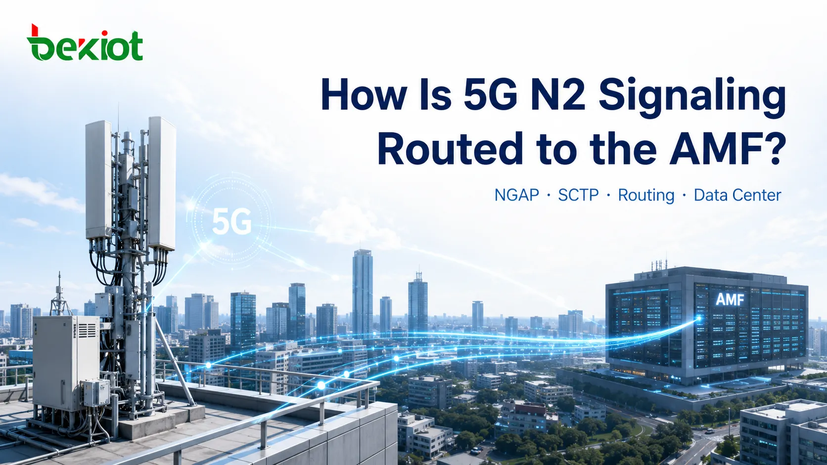
When capturing 5G registration signaling, engineers can usually find messages such as Initial UE Message, Uplink NAS Transport, and other NGAP procedures without much difficulty. The harder question is often what happens underneath: how does an N2 signaling packet leave the gNB, cross the transport network and data center, and finally reach the server hosting the AMF service? If the AMF has been virtualized and runs inside a VM, what endpoint is the gNB actually establishing its SCTP association with? What roles do the PTN gateway, data-center edge router, EOR switch, and TOR switch play? And when signaling fails, should troubleshooting begin with NGAP, SCTP, IP routing, or Layer 2 MAC forwarding?
These questions appear to belong to different engineering domains. The radio team focuses on the gNB, the core-network team looks at the AMF and NGAP, the transport team manages the PTN, and the data-center team is responsible for switches and servers. In a working N2 path, however, all of these components operate as one continuous chain. A NAS Registration Request received by the gNB does not simply “jump” to the AMF. The gNB first relays the message from the RRC side into NGAP, encapsulates it over SCTP and IP, sends it through multiple Layer 3 and Layer 2 network nodes, and ultimately delivers it into the compute environment where the AMF process is running. N2 routing becomes much easier to troubleshoot when the logical protocol path and the physical network path are viewed together rather than reduced to a simple “Can I ping the AMF?” test.
What Is the N2 Interface Actually Forwarding?
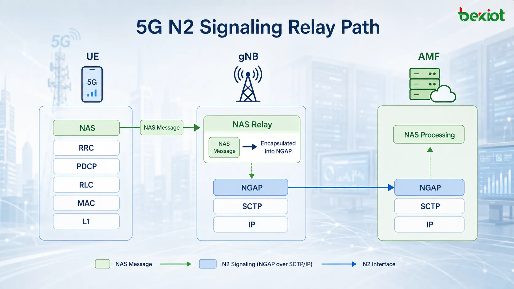
N2 is the signaling interface between the gNB and AMF. For UE registration, mobility management, and other 5G control-plane procedures, the UE generates NAS messages while the gNB performs a critical relay function. It takes the NAS-PDU received from the UE, carries it inside the appropriate NGAP message, and sends it toward the AMF over N2. The reverse process applies in the downlink direction. Understanding N2 signaling therefore requires separating the application message itself from the transport path that carries it.
Consider a UE initiating registration. The UE first sends a NAS Registration Request through the radio protocol stack toward the gNB. For this type of signaling, the gNB is not the final application endpoint. Its role is to place the NAS-PDU into an NGAP message and forward it over the already established N2 transport relationship toward the AMF. At a high level, the UE side processes the message through NAS, RRC, PDCP, RLC, MAC, and L1. At the gNB, the NAS message is relayed from the radio-side stack into NGAP and then carried over SCTP, IP, Layer 2, and Layer 1. At the AMF, the packet is decapsulated through the reverse stack until the NAS message reaches the NAS processing layer.
One common misunderstanding is to treat “the gNB forwarding NAS” as the same type of forwarding performed by an IP router. They happen at different layers. The gNB first performs a protocol-level relay from NAS/RRC into NGAP and creates a new N2-side SCTP/IP packet. The transport network and data-center network do not need to understand whether the payload contains a Registration Request or another NAS procedure. Their job is simply to move the packet according to IP routing, MAC addressing, and interface information.
NGAP procedures can also be divided into UE-associated and non-UE-associated categories. NAS Transport and Initial Context Setup are UE-associated procedures, while NG Setup is a node-level, non-UE-associated procedure. This distinction is useful during troubleshooting. If every UE on a gNB is unable to communicate with the AMF, the first suspects should be the node-level N2 relationship, SCTP, and IP routing. If only one UE is affected, the investigation should continue along that UE's NGAP and NAS context.
Which Network Nodes Does N2 Signaling Cross Between the gNB and AMF?
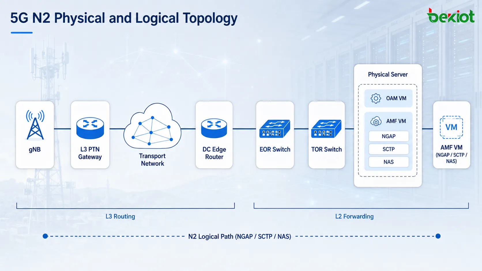
Logical architecture diagrams often show N2 as a single line between the gNB and AMF. That representation is useful for explaining the interface relationship, but it does not show the actual network path taken by signaling traffic. In a real deployment, a gNB is rarely connected directly to an AMF server with a single physical link. A transport network sits between the RAN and the core data center, while routers, switches, and server networking are used inside the data center itself.
A simplified N2 transport path can be represented as follows: the gNB sends traffic to a Layer 3 PTN gateway, the packet crosses the transport network and reaches the Layer 3 data-center edge router, then passes through EOR and TOR switches before finally arriving at the server hosting the AMF. The PTN transports the gNB-side IP traffic toward the regional or central data center. The Layer 3 router at the data-center boundary then routes the N2 packet toward the correct server network. Inside the data center, the EOR and TOR switches perform Layer 2 switching until the Ethernet frame reaches the server interface carrying the AMF workload.
In a cloud-based 5G Core, the question “Which device is the AMF on?” cannot be answered purely in terms of a physical server. The AMF may run as a virtualized network function on a general-purpose compute node, and the same physical server may also host OAM virtual machines, other network functions, or multiple service instances. For example, one VM may run the AMF service responsible for NAS, NGAP, and SCTP processing. From the gNB's perspective, however, the important information is the N2 service IP endpoint exposed by the AMF, not the physical server label on the rack.
This means N2 troubleshooting involves at least three different notions of location. The physical location identifies the rack and physical host where the workload runs. The logical location identifies the VM or service instance hosting the AMF. The network location is the AMF N2 IP address used by the gNB when establishing the SCTP association. It is entirely possible for the physical server, VM, and AMF process to appear healthy while N2 remains unreachable because the VLAN, default gateway, IP route, switch port, or virtual switching layer does not correctly deliver traffic to that N2 address.
What Is the Difference Between Routing and Forwarding on the N2 Path?
Delivering an N2 signaling packet to the AMF involves more than simply having a routing table. From a network-processing perspective, it is important to distinguish between routing and forwarding. Routing is generally a Layer 3 function. When a device receives an IP packet, it looks up the destination IP address in its routing table, determines the outgoing interface, and selects the appropriate next hop. Along the N2 path, the gNB, Layer 3 PTN gateway, and data-center edge router all need the relevant IP routing information. Those routes may be configured statically or learned through a dynamic routing protocol.
Assume the gNB N2 source address is A and the AMF N2 address is B. The gNB does not need to know which physical server rack contains B. It only needs to know which next-hop gateway should receive packets destined for the subnet containing B. Layer 3 devices in the PTN make the same decision using their own routing tables until the packet enters the data-center network containing the AMF.
Routing determines where the packet should go next, but the packet still has to be transmitted over the current physical link. If Ethernet is used, the device adds an Ethernet frame header containing source and destination MAC addresses. The switch then forwards the frame according to its MAC address table. As a result, the outer Layer 2 header of the same N2 IP packet can change as it crosses different Layer 3 hops. The IP layer continues to represent the end-to-end relationship between the gNB and AMF, while the MAC addresses are relevant only to the current Layer 2 segment.
Within the data center, EOR and TOR switches primarily perform Layer 2 switching. Once the Layer 3 data-center router has delivered the N2 packet into the correct server-side Layer 2 domain, the EOR and TOR switches use their MAC tables to move the frame toward the target server port. This distinction is important during packet analysis. Different MAC addresses at different capture points do not mean that the packet changed its final destination, and unchanged source and destination IP addresses do not mean the packet traveled directly between the two endpoints without crossing intermediate devices.
Why Is the SCTP Association the Key Boundary in N2 Troubleshooting?
NGAP does not run directly over IP. It runs over SCTP. A usable N2 path therefore requires IP reachability first, followed by successful SCTP association establishment. This creates a clear troubleshooting dependency: if IP routing is broken, SCTP cannot be established; without SCTP, NGAP cannot operate; and without NGAP, NAS signaling cannot be relayed successfully.
The reverse, however, is not necessarily true. Being able to ping the AMF only demonstrates some level of IP reachability. It does not prove that the required SCTP service is reachable, that the SCTP association can be established, that NGAP parameters are correct, or that the AMF application process is functioning normally.
First, verify the IP path. Check the gNB N2 address, subnet mask, default gateway, and route toward the AMF N2 address. Then verify that the PTN gateway and data-center Layer 3 devices have both the forward route and the return route. Return routing is particularly easy to overlook. A packet leaving the gNB may reach the AMF successfully while the AMF still has no valid route back to the gNB subnet. Because N2 is a bidirectional signaling interface, both directions must work.
Second, confirm that SCTP is actually established. Once IP reachability is verified, check whether the gNB and AMF complete the SCTP association procedure and enter the Established state. If the association never comes up, inspect transport-layer ports, local IP bindings, ACLs, firewalls, and any security policy applied along the path. Real data centers may also include IDS/IPS, load balancers, SDN components, or other security and traffic-control systems that can affect SCTP even when simplified architecture diagrams do not show them.
Third, move up to NGAP and NAS. NG Setup, Initial UE Message, and NAS Transport should only be analyzed after the SCTP association is stable. If SCTP is working but NG Setup fails, the problem has moved above the IP transport layer into N2 application or configuration logic. If NG Setup succeeds but a particular UE's registration signaling does not reach the AMF, continue by tracing the Initial UE Message, UE-NGAP-ID values, and NAS-PDU. This layered approach avoids a common mistake: starting with NAS troubleshooting before confirming that the NAS message actually crossed the N2 interface.
How Can a Packet Capture Reconstruct the Full N2 Signaling Path?
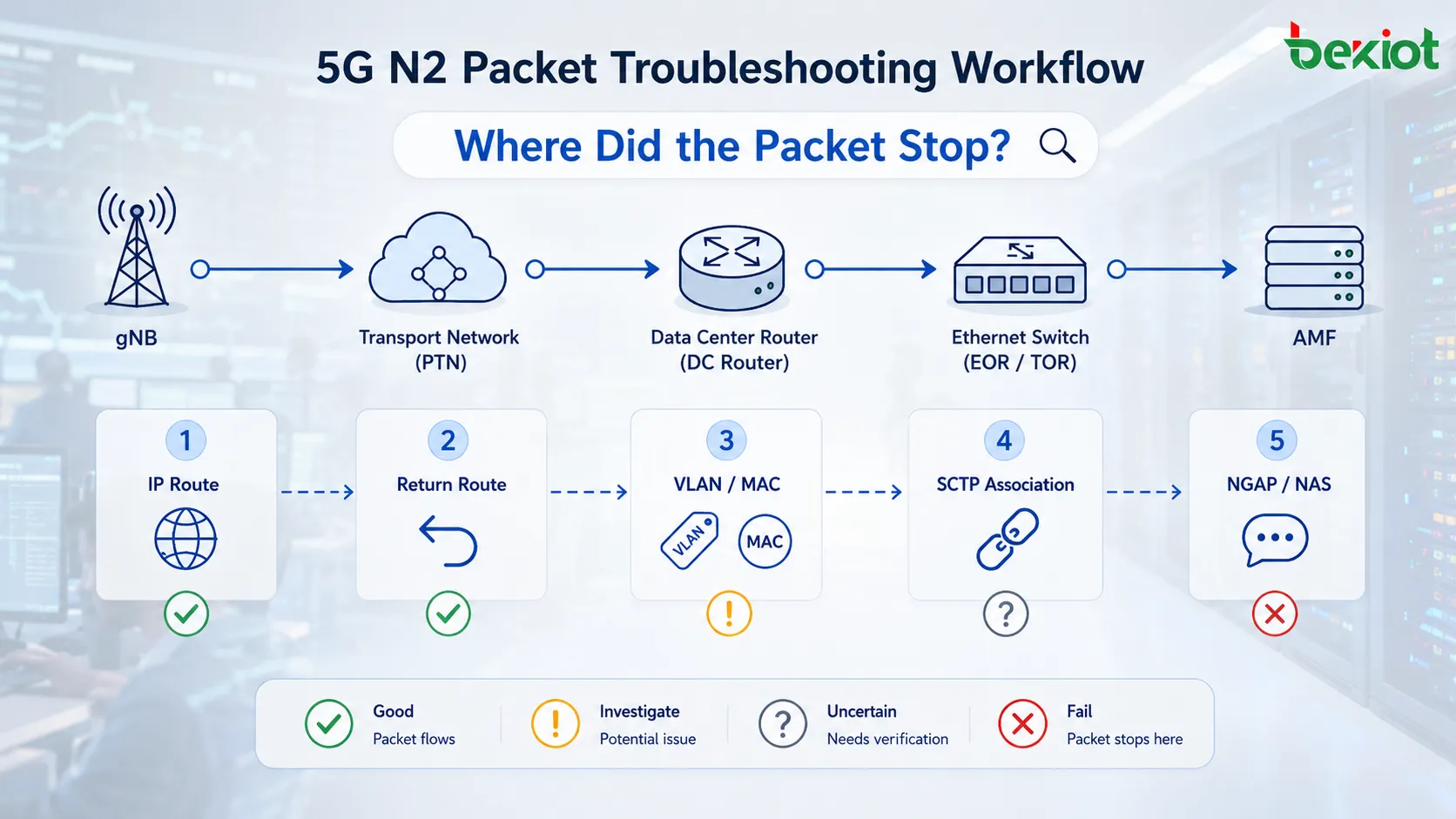
The real value of understanding N2 routing appears during packet capture and fault isolation. When troubleshooting a case where signaling between the gNB and AMF is failing, the path should be checked from the transport layers upward. Capture location matters. A trace on the gNB side confirms whether signaling actually leaves the base station. A capture near the PTN or data-center edge helps determine whether the packet enters the core-network region. A server-side capture shows whether the N2 packet physically reaches the host running the AMF workload. If the gNB-side trace shows SCTP INIT packets being transmitted while the AMF host never sees them, the fault is almost certainly somewhere in the intermediate network rather than in NGAP application logic.
After capturing the packet, verify that the source and destination IP addresses match the intended design. If the AMF was migrated, scaled out, or moved to a new VM while the gNB still points to an old N2 address, signaling may follow the wrong path even though the NGAP configuration appears otherwise unchanged. Next, inspect the route hop by hop across the Layer 3 devices. On the gNB, PTN gateway, and data-center router, check the route toward the AMF subnet, including the outgoing interface, next hop, and return path. If dynamic routing is used, confirm that the route has actually been learned and installed in the forwarding table rather than merely verifying that the routing protocol is enabled in configuration.
Once the packet reaches the data-center Layer 3 boundary but still fails to reach the AMF server, the troubleshooting focus shifts from IP routing to Layer 2 forwarding. Check VLAN membership on the EOR and TOR switches, MAC address learning, server-facing port status, and whether the server or virtual switching layer is attached to the correct service network. Finally, correlate the network findings with SCTP state. If the bidirectional IP path is healthy but SCTP still cannot establish, investigate SCTP port handling, IP binding, and the AMF process itself. Once SCTP is established, NGAP and NAS analysis can proceed with a much clearer fault boundary.
Viewed end to end, “N2 signaling routing” actually consists of two different but continuous processes. The first occurs inside the gNB. A NAS message arrives from the UE over the radio side, is relayed into an NGAP message, and is then encapsulated over SCTP and IP so that it can be transported across the N2 network.
The second process occurs inside the transport network and data center. These network devices do not care whether the payload contains a Registration Request or an Initial Context Setup procedure. They use Layer 3 IP routing and Layer 2 MAC forwarding to move the packet hop by hop toward the compute environment running the AMF service.
For practical engineering, the most effective way to troubleshoot N2 is therefore to maintain an end-to-end view:
UE NAS → gNB Relay → NGAP → SCTP → IP Routing → Layer 2 Forwarding → AMF Server → AMF Process
Once that chain is followed layer by layer, many problems that initially look like complex “registration failures,” “N2 unreachable” faults, or “SCTP association failures” can be reduced to a much more specific question: at which layer and at which hop did the packet stop?
FAQ
Does N2 Signaling Pass Through the UPF?
Under normal 5G architecture, the N2 control-plane path does not rely on the UPF. N2 connects the gNB and AMF, while the UPF primarily participates in the user-plane path. When N2 is unreachable, troubleshooting should focus on the control-plane transport path between the gNB and AMF rather than starting with the N3 user-plane tunnel.
Why Do MAC Addresses Change When Capturing the Same N2 Packet at Different Points?
MAC addresses belong to the current Layer 2 segment. After a packet crosses a Layer 3 routing device, it is encapsulated with a new Layer 2 header for the next link. The source and destination MAC addresses can therefore change from hop to hop even though the end-to-end gNB and AMF IP addresses remain associated with the same N2 communication flow.
Why Can SCTP Still Fail Even If the gNB Can Ping the AMF?
Ping mainly verifies ICMP-based IP reachability. SCTP also depends on transport-layer port handling, local IP binding, ACLs, firewalls, security policies, and the AMF application process. IP reachability is therefore only a prerequisite for N2 communication and does not guarantee that SCTP or NGAP is functioning correctly.
If the AMF Runs in a Virtual Machine, Does the gNB Need to Know the Physical Server Location?
No. The gNB establishes the N2 connection using the AMF's N2 service IP address rather than the physical server location. The physical host, virtual switch, VM mapping, and internal data-center topology are implementation details, but they must still deliver packets addressed to the AMF N2 endpoint to the correct service instance.
Why Should Both Forward and Return Routes Be Checked for N2 Problems?
NGAP and SCTP are both bidirectional. Even if packets from the gNB can reach the AMF, the SCTP handshake and subsequent NGAP procedures will still fail if the AMF has no valid route back to the gNB subnet. One-way reachability is therefore not enough to prove that the N2 path is complete.