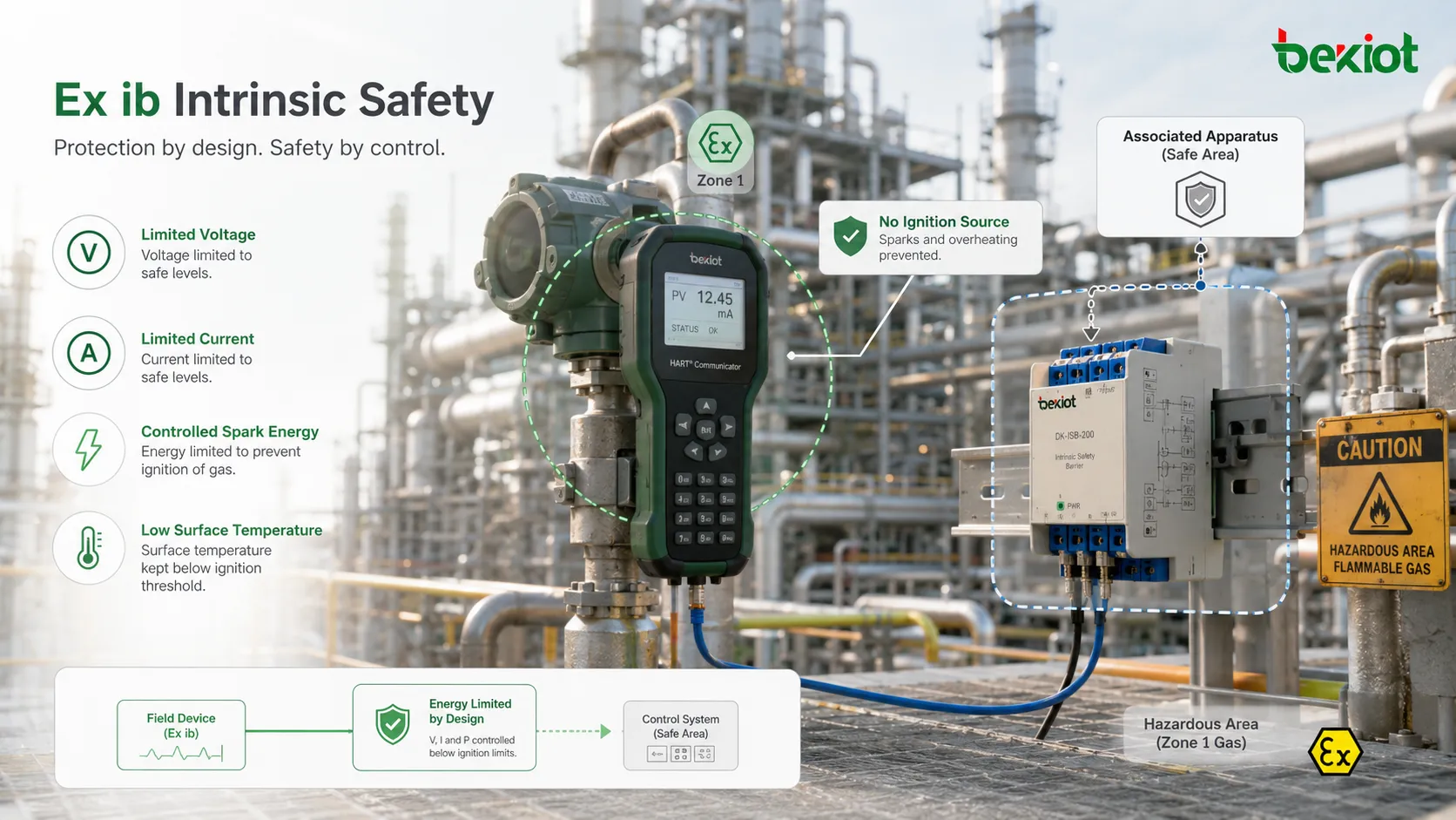
Ex ib is an intrinsic safety protection level used for electrical equipment and circuits intended for hazardous areas where explosive gas atmospheres may occur during normal operation. The purpose of this protection method is to limit electrical and thermal energy so that sparks, arcs, or hot surfaces cannot ignite the surrounding atmosphere under defined conditions.
Unlike flameproof protection, which contains an internal explosion, intrinsic safety focuses on preventing ignition energy from being available in the first place. This makes it especially useful for instrumentation, sensors, transmitters, portable devices, control circuits, low-power communication interfaces, measurement loops, and field devices installed in process plants, chemical areas, refineries, tank farms, utilities, and industrial automation systems.
Quality Starts with Ignition Prevention
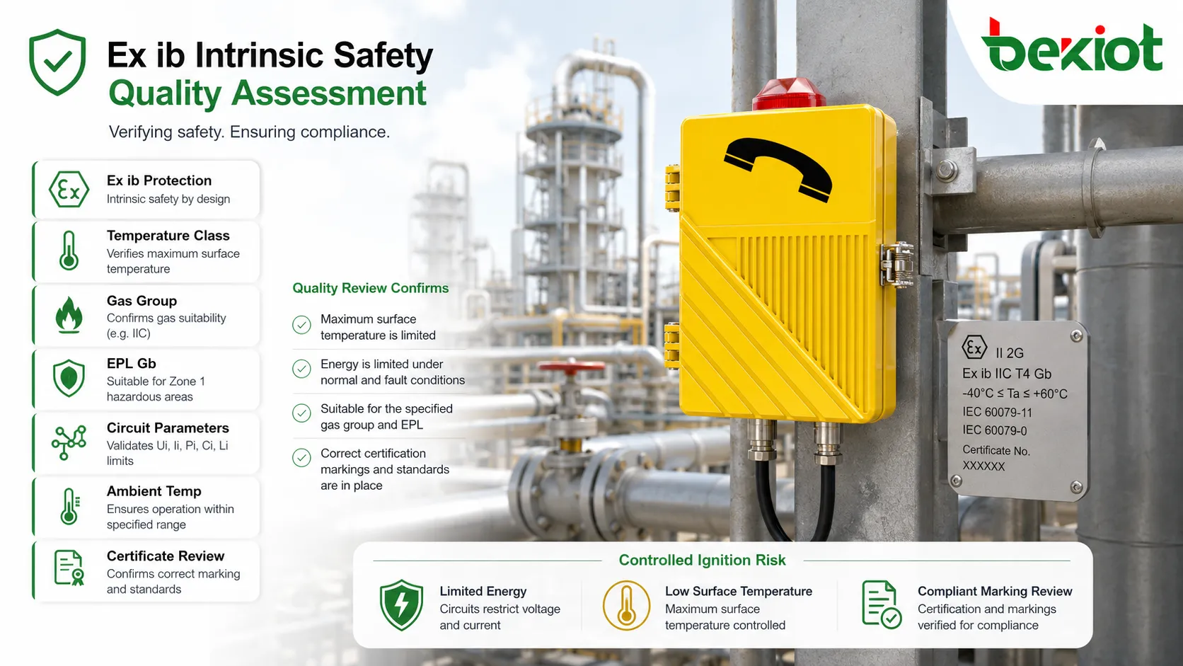
The quality target of an Ex ib design is not simply that the equipment works electrically. It must remain non-ignitive under normal operation and under the fault conditions required for this protection level. This means every circuit, component, conductor, enclosure interface, terminal, battery, connector, and associated apparatus must be evaluated as part of an ignition-risk control system.
Quality standards therefore look beyond ordinary product performance. They examine whether the equipment can limit voltage, current, power, stored energy, surface temperature, and fault energy before these values become dangerous in a defined explosive atmosphere.
This is why Ex ib products require certified design, controlled manufacturing, documented assessment, correct marking, and verified installation. A device cannot be treated as intrinsically safe only because it is low voltage or low power.
Standards Framework Behind Compliance
General Equipment Requirements
General explosion-protection requirements define how Ex equipment should be constructed, tested, marked, and documented. These requirements cover topics such as equipment grouping, temperature classification, marking format, mechanical design, environmental suitability, instructions, and certificate conditions.
For manufacturers and buyers, this means quality must be visible in the product identity. The marking should show the protection concept, gas group, temperature class, equipment protection level, certificate reference, and any special conditions of use where applicable.
Intrinsic Safety Requirements
The intrinsic safety standard focuses on how circuits are kept non-ignitive. It addresses electrical parameters, spark ignition risk, thermal ignition risk, separation distances, protective components, energy storage, batteries, transformers, opto-isolators, semiconductors, connectors, and associated apparatus.
For Ex ib, the circuit must meet the required protection level under the defined fault condition. The design should not rely on assumptions or user behavior. It must be proven through calculation, assessment, component selection, construction rules, and testing.
Installation and System Standards
Intrinsic safety is often a system-level concept. A field device, cable, barrier, isolator, grounding method, terminal block, and control-room interface must be compatible. Installation standards guide how intrinsically safe circuits should be installed, separated, identified, earthed, and maintained.
A certified field device can be installed incorrectly if the associated apparatus is mismatched, cable parameters exceed allowed values, or intrinsic safety wiring is mixed with non-intrinsically safe circuits.
Regional Certification Schemes
Projects may require IECEx, ATEX, UKCA, North American hazardous location approvals, or other local certification systems. The same technical concept may appear with different certificate formats, marking conventions, inspection requirements, and legal obligations.
Quality review should therefore include both the technical standard and the target market. A product suitable for one certification regime may still need additional documentation or approval for another region.
Protection Level and Area Suitability
Ex ib is generally used where a high level of protection is required, commonly associated with Zone 1 gas environments and EPL Gb equipment. In practical terms, this means the atmosphere is not continuously explosive, but explosive gas may occur during normal operation.
It is important not to confuse Ex ib with Ex ia or Ex ic. Ex ia provides a higher level of intrinsic safety and may be suitable for more severe zones when properly certified. Ex ic provides a lower level and is generally associated with less hazardous conditions. The correct level must match the area classification.
Area suitability should be determined by hazardous area classification, gas group, temperature class, equipment protection level, installation method, and the complete loop assessment. The marking on the product is only one part of the decision.
| Protection Level | Typical Gas Area Suitability | Fault Expectation | Main Quality Concern |
|---|---|---|---|
| Ex ia | Often used for Zone 0, Zone 1, and Zone 2 when certified accordingly. | Designed for higher fault tolerance. | Maximum ignition prevention for the most demanding exposure. |
| Ex ib | Commonly associated with Zone 1 and Zone 2 applications. | Designed to remain safe under the required single-fault condition. | Correct energy limitation, certified parameters, and installation compatibility. |
| Ex ic | Commonly associated with Zone 2 applications. | Focused mainly on normal operation protection. | Use only where the hazardous area classification allows it. |
Energy-Limiting Design Requirements
Voltage and Current Control
The core of intrinsic safety is limiting voltage and current in the hazardous-area circuit. This may be achieved through resistors, fuses, Zener diodes, galvanic isolation, current limiting circuits, controlled power supplies, or certified associated apparatus.
Quality depends on predictable behavior under fault conditions. Components used for protection must have appropriate ratings, reliability, spacing, and failure assumptions. Ordinary circuit design margins are not enough when ignition prevention is the purpose.
Stored Energy Limitation
Capacitors and inductors can store energy. Even if the supply voltage is low, stored energy can discharge as a spark under certain conditions. Therefore, capacitance and inductance must be assessed carefully.
The evaluation includes internal component values and external cable parameters. Long cables can add capacitance and inductance, so the certified loop parameters must not be exceeded during installation.
Power Dissipation Control
Electrical power can create heat. Heat may appear in resistors, semiconductors, batteries, coils, terminals, or faulted components. The design must ensure that surface temperature remains below the permitted temperature class under the required conditions.
This is why thermal assessment is part of quality control. A circuit that cannot spark may still be unsafe if it creates a hot surface capable of ignition.
Protective Component Reliability
Protection components must be selected and applied with care. A protective resistor, fuse, diode, optocoupler, transformer, or isolator should not be treated as a normal commodity part without considering its safety role.
Quality review should check component derating, failure mode, certification suitability, creepage and clearance, temperature rise, and whether the component is allowed to be counted as an infallible or safety-related part under the applicable rules.
Temperature Class and Surface Safety
Temperature class is one of the most important markings on Ex equipment. It indicates the maximum surface temperature limit under defined conditions. The selected equipment must have a temperature class suitable for the ignition temperature of the gas or vapor present at the site.
For Ex ib equipment, thermal safety must be evaluated during normal operation and the required fault condition. Components should not exceed the permitted temperature even if a fault causes higher dissipation in a limited part of the circuit.
Ambient temperature range also matters. A device certified for one ambient range may not be suitable for a hotter or colder location unless the certificate and marking allow it.
Gas Group and Ignition Sensitivity
Gas groups classify explosive atmospheres according to ignition characteristics. Equipment marked for a more demanding gas group may be suitable for less demanding groups, but this must be verified from the marking and certificate.
For intrinsic safety, gas group affects permitted electrical energy. More easily ignited gases require stricter energy limitation. This is why the same circuit may be acceptable for one gas group but not another.
Quality standards require the manufacturer and installer to match the product marking with the actual hazardous substance at the site. The wrong gas group selection can make an otherwise certified product unsuitable for the application.
Certified Parameters for Field Loops
Input and Output Values
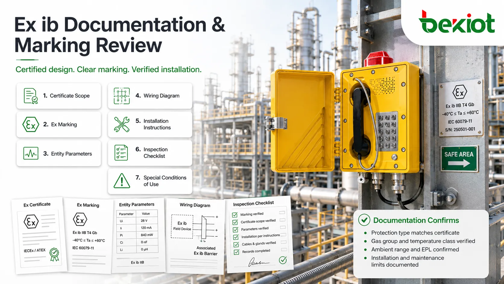
Intrinsic safety loops are often checked using parameters such as maximum input voltage, maximum input current, maximum input power, maximum internal capacitance, maximum internal inductance, and corresponding output parameters from associated apparatus.
These values help determine whether a field device, cable, and barrier or isolator can be safely connected together. The loop must be assessed as a complete system, not as separate approved items.
Cable Capacitance and Inductance
Cables are part of the safety calculation. Their capacitance and inductance may increase with length and construction type. If cable parameters are ignored, the total stored energy may exceed the certified limit.
Installation documentation should record cable type, length, route, and calculated or specified parameters when required.
Associated Apparatus Compatibility
Barriers and isolators are often located in a safe area but connect to circuits entering a hazardous area. They must be compatible with the field device and circuit parameters.
A barrier does not automatically make any circuit intrinsically safe. The complete combination must satisfy the permitted values and installation rules.
Manufacturing and Quality Control
Controlled Production Process
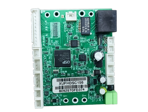
Certified equipment must be manufactured consistently. The production process should ensure that safety-related parts, PCB layout, separation distances, component ratings, potting, connectors, labels, and enclosure materials match the certified design.
Substituting components without assessment can invalidate safety assumptions. Even a small component change may affect fault behavior, temperature rise, or stored energy.
Routine Inspection
Routine inspection may include visual checks, label verification, component verification, PCB inspection, enclosure integrity, terminal inspection, insulation checks, firmware version control, and functional tests.
These checks help ensure that every production unit matches the certified design rather than only the prototype tested during certification.
Traceability
Traceability connects each product to its production records, certificate, component batches, test results, firmware, and quality inspection data. This is important when a field issue, recall, design update, or certificate change occurs.
Without traceability, it is difficult to know which units may be affected by a production or component problem.
Change Control
Any change to safety-related components, PCB layout, enclosure material, battery type, connector, cable entry, firmware behavior, or marking should go through formal review. If the change affects the certified design, certificate update or reassessment may be required.
Change control is a key quality standard because Ex safety relies on the exact construction that was evaluated.
Marking and Documentation Review
Ex marking should be clear, durable, and consistent with the certificate. It should communicate the protection type, equipment group, gas group, temperature class, EPL, certificate number, ambient range if applicable, and special conditions where required.
Documentation should include installation instructions, safety parameters, entity parameters, wiring diagrams, maintenance limitations, special conditions of use, environmental limits, and repair restrictions.
For end users, documentation is not optional paperwork. It is part of the safety system. Installers use it to decide where and how the equipment can be used, and inspectors use it to verify compliance.
Installation Quality Requirements
Separation from Non-IS Circuits
Intrinsically safe circuits must be separated from non-intrinsically safe circuits according to the installation rules. Poor separation can allow dangerous energy to enter the protected circuit.
Separation may involve physical distance, partitions, dedicated cable trays, marked terminals, blue wiring practices, certified barriers, or approved installation methods.
Grounding and Bonding
Some Zener barrier systems require reliable grounding to operate correctly. Galvanic isolators may reduce grounding dependency, but grounding and bonding still need review for the complete system.
Improper grounding can compromise protection, create noise problems, or produce unsafe voltage differences between circuits.
Correct Cable Entries and Terminals
Cable glands, terminal blocks, connectors, and enclosure entries should match the certification and installation environment. A certified device may become non-compliant if unsuitable cable entries are used.
Installers should follow certificate conditions, environmental rating, mechanical protection requirements, and hazardous area wiring rules.
Inspection Before Energizing
Before power is applied, the installation should be checked for correct device marking, area suitability, cable routing, barrier compatibility, loop parameters, grounding, separation, terminal tightness, and documentation availability.
This inspection helps catch errors before the system becomes operational in a hazardous area.
Where This Protection Level Is Applied
Process Instrumentation
Pressure transmitters, temperature sensors, flowmeters, level instruments, gas detectors, and measurement loops commonly use intrinsic safety because they often require low-power signals in hazardous areas.
Ex ib may be selected where the area classification and protection level allow it, especially in Zone 1 applications requiring robust but practical field wiring.
Industrial Automation Interfaces
PLC input/output modules, signal isolators, communication converters, operator indicators, and low-power control interfaces may use intrinsically safe circuits to connect field devices in hazardous zones.
The system must be evaluated from the control cabinet to the field device, including cables and associated apparatus.
Portable and Handheld Equipment
Handheld testers, portable communication devices, inspection tools, calibration instruments, and maintenance devices may need Ex certification when used in hazardous areas.
Battery safety, enclosure durability, charging restrictions, and user instructions are especially important for portable devices.
Remote Monitoring and Telemetry
Tank farms, pipelines, chemical storage areas, wastewater facilities, and energy sites may use low-power telemetry equipment in hazardous locations. Intrinsic safety can support sensor communication while limiting ignition risk.
Wireless devices still require careful battery, antenna, RF power, enclosure, and temperature assessment.
Common Non-Conformities
Using the Wrong Protection Level
Using equipment certified for a less demanding area in a more hazardous zone is a serious error. The protection level must match the classified area and hazardous substance.
Mixing Certified and Non-Certified Components
Replacing a certified barrier, connector, battery, or cable assembly with an ordinary part may invalidate the intrinsic safety assessment.
Ignoring Cable Parameters
Long field cables can add capacitance and inductance. If these values exceed the allowed parameters, the loop may no longer meet safety requirements.
Missing Special Conditions of Use
Certificates may include special conditions. These can relate to installation orientation, electrostatic risk, impact protection, ambient temperature, cable entries, or maintenance restrictions.
Poor Label Durability
If markings become unreadable, inspectors and maintenance personnel may not be able to verify equipment suitability. Durable marking is part of quality compliance.
Ex ib quality is proven through a complete chain: certified design, controlled manufacture, correct marking, compatible loop parameters, proper installation, and documented inspection.
Maintenance and Periodic Verification
Maintenance should preserve the certified safety condition. Technicians should not modify circuits, replace components, change batteries, alter cable entries, or repair boards unless the procedure is permitted by the certificate and manufacturer instructions.
Periodic inspection should confirm that labels remain legible, enclosure condition is acceptable, cable glands are intact, terminals are secure, barriers are correct, wiring separation remains in place, and environmental damage has not occurred.
When equipment is relocated, reused, or connected to a different system, the loop assessment should be repeated. A device suitable in one circuit may not be suitable in another circuit if associated apparatus or cable parameters change.
FAQ
Can Ex ib equipment be used in Zone 0?
Usually no. Zone 0 normally requires a higher protection level such as Ex ia when intrinsic safety is used. Always check the certificate, marking, and area classification.
Does low voltage automatically mean intrinsically safe?
No. Intrinsic safety depends on certified energy limitation, fault assessment, temperature control, construction rules, and system compatibility, not just a low nominal voltage.
Can a damaged intrinsically safe device still be used?
No. Visible damage, unreadable marking, cracked enclosure, loose terminals, or suspected internal fault should be investigated before the device is returned to service.
Why are cable parameters included in loop calculations?
Cables add capacitance and inductance, which can store energy. The complete circuit must remain within the certified limits for the selected field device and associated apparatus.
Who should verify an Ex ib installation?
Verification should be performed by competent personnel familiar with hazardous area classification, intrinsic safety loops, applicable standards, certificate conditions, and local installation rules.