In voice communication and unified communication projects, connecting a telephone system to the public switched telephone network is still a common requirement. For larger sites that need many telephone channels, centralized numbering, and stable trunk access, an E1 digital trunk gateway is often used to bridge legacy telecom lines with modern PBX, IPPBX, SIP, or dispatch communication platforms.
E1 wiring looks simple from the outside, but many on-site problems come from misunderstanding the physical interface. An E1 line is not wired like an ordinary Ethernet connection. It uses separate transmit and receive paths, and the correct wiring method depends on whether the line side is 120-ohm balanced RJ45 or 75-ohm unbalanced BNC. A practical installation plan should confirm the interface type, wiring sequence, transmission direction, grounding, distance, and gateway status indicators before commissioning.
Where This Connection Fits in a Voice Project
An E1 digital trunk is commonly used when a project needs to connect a PBX or IP communication platform to a carrier-side PSTN trunk. It is suitable for enterprises, campuses, hotels, hospitals, industrial parks, command centers, and call service environments where many telephone channels must be carried through a centralized trunk link.
A standard E1 telephone trunk can generally carry 30 voice channels. This makes it more efficient than deploying many separate analog lines when the project requires multiple outside-line calls, unified dialing rules, centralized number resources, or trunk-level voice integration.
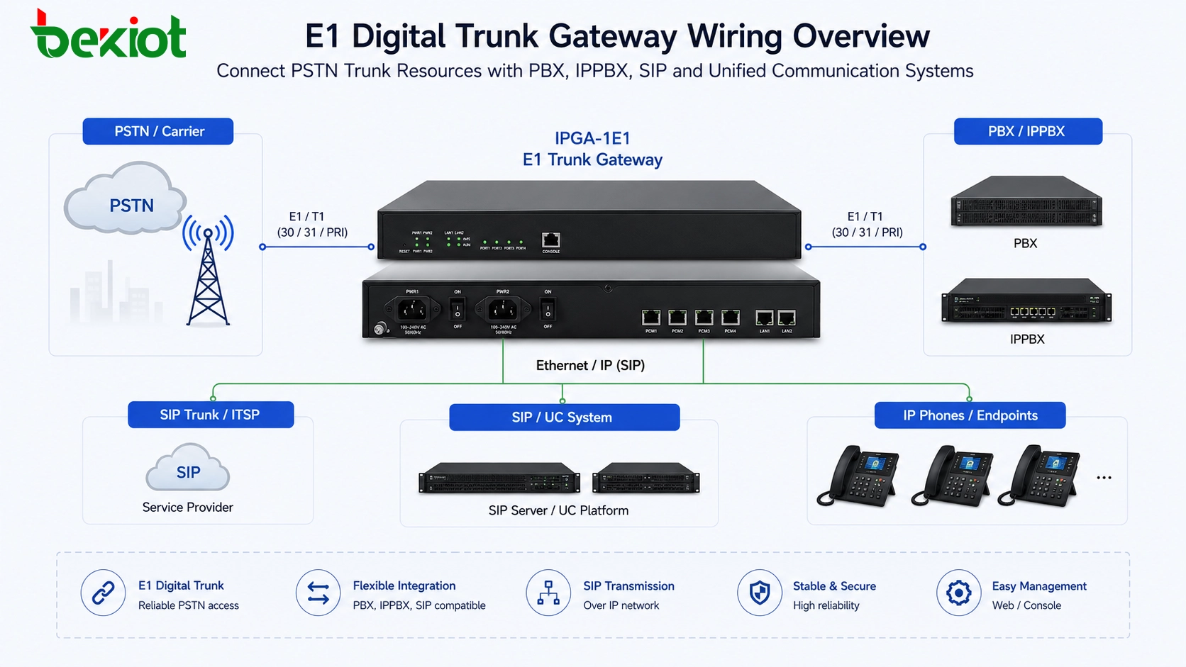
In a modern architecture, the E1 side connects to the carrier, legacy PBX, or digital trunk equipment, while the gateway side converts the service into a form that can be used by IPPBX, SIP servers, dispatch consoles, recording platforms, and other communication applications. The physical connection is the foundation of the whole integration. If the E1 link layer is not established, later SIP configuration, dial plan adjustment, and number routing will not work reliably.
Two Interface Types to Confirm First
The first thing to check is whether the E1 interface is 120-ohm balanced or 75-ohm unbalanced. These two wiring methods are both used in real telecom projects, but their connectors and cable types are different.
A 120-ohm E1 interface usually uses an RJ45-style connector and twisted-pair wiring. Although the connector may look similar to a network port, it is not an Ethernet port and should not be treated as one. Only specific pins are used for E1 transmit and receive signals.
A 75-ohm E1 interface usually uses coaxial cable with BNC connectors. In this design, one BNC connector is used for receiving data and the other is used for transmitting data. Because coaxial shielding and grounding are involved, installation quality and grounding conditions should be checked carefully.
The gateway, carrier device, PBX trunk card, or transmission equipment must use compatible impedance and interface type. If one side is 75-ohm BNC and the other side is 120-ohm RJ45, an appropriate impedance adapter or conversion cable is required.
Related Product: Becke IPGA-1E1 Trunk Gateway
Understanding Transmit and Receive Direction
E1 telephone links normally use a four-wire transmission concept. Two wires are used for receiving data, and two wires are used for transmitting data. This transmit-and-receive relationship is the key point in E1 wiring.
When two E1 devices are connected, the transmit side of one device must connect to the receive side of the other device. In simple terms, TX should connect to RX, and RX should connect to TX. If both sides are connected transmit-to-transmit or receive-to-receive, the link will not establish correctly.
This is different from how many installers think about ordinary network cables. For Ethernet cabling, users often focus on whether the cable is straight-through or crossed according to network port behavior. For E1 wiring, the transmit and receive direction must be understood clearly because the interface does not work as a general network port.
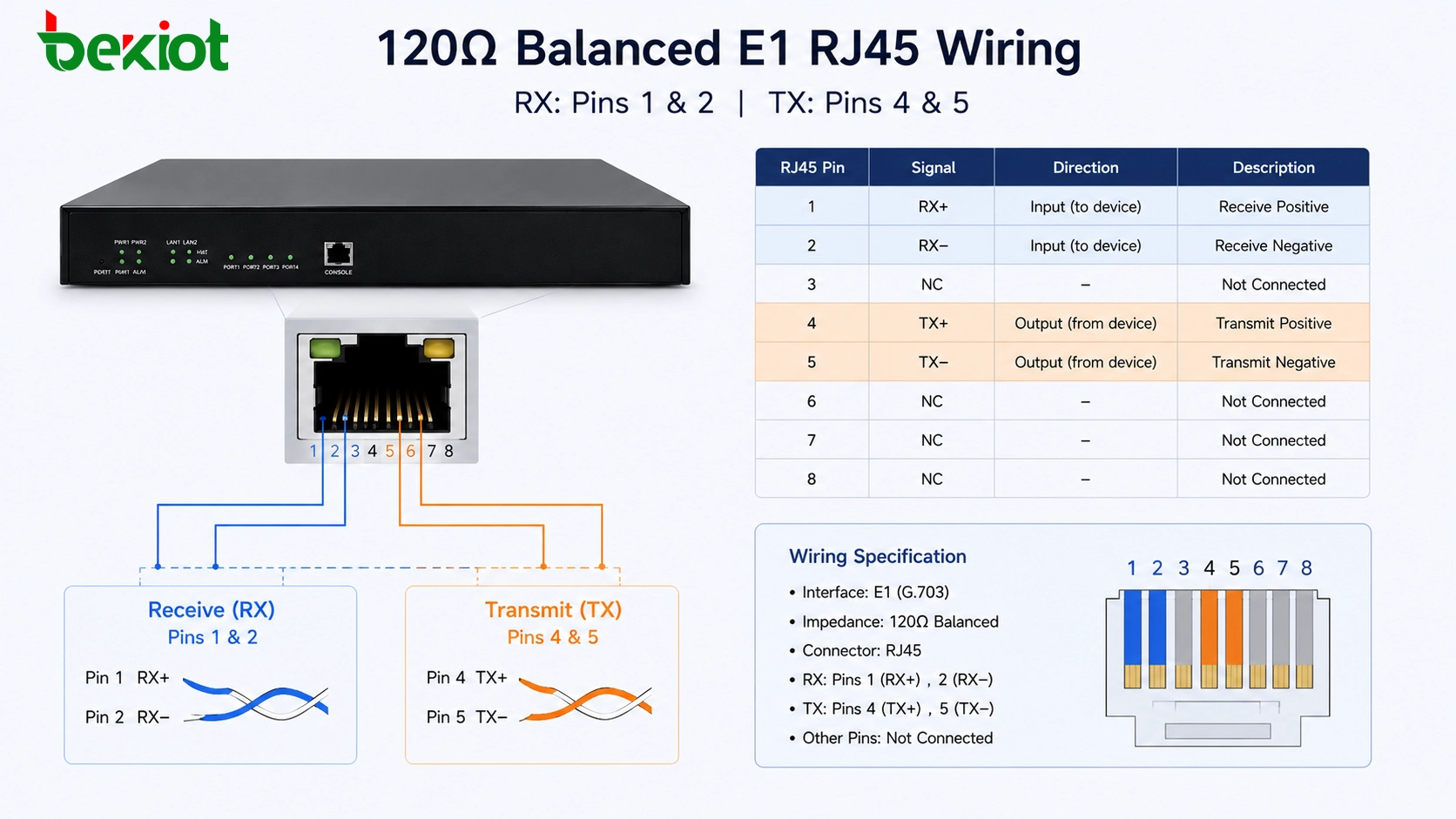
RJ45 Wiring for 120-Ohm Balanced E1
For a 120-ohm balanced E1 interface, the connection is commonly made through an 8-pin crystal connector, similar in appearance to an RJ45 plug. However, the E1 link only uses four pins: 1, 2, 4, and 5.
A common wiring method is: pins 1 and 2 for receiving data, and pins 4 and 5 for transmitting data. When connecting to another E1 device, the receive pair on one side should match the transmit pair on the other side. This means that cross-connection may be required depending on the pin definition of the opposite device.
If the carrier provides an E1 handoff through a crystal-head interface, this 120-ohm wiring method is often used. During commissioning, if the wiring direction is uncertain, technicians commonly prepare two cables with opposite TX/RX arrangements and test which one brings the E1 link up. This is a practical troubleshooting method when documentation is incomplete.
BNC Cabling for 75-Ohm Unbalanced E1
Another common E1 wiring method is the 75-ohm unbalanced coaxial connection. This method uses BNC connectors and coaxial cables. The E1 device normally provides two BNC ports: one for receive and one for transmit.
The wiring principle remains the same. The receive port of one device should connect to the transmit port of the opposite device, and the transmit port should connect to the receive port of the opposite device. In other words, the signal direction must be crossed between both ends.
For BNC coaxial wiring, the center conductor carries the signal, while the shield layer is used for grounding. Because of this structure, both equipment grounding and cable quality can affect link stability. Poor grounding, loose BNC connectors, damaged coaxial cable, or incorrect TX/RX direction may cause link failure, intermittent alarms, or unstable voice channels.
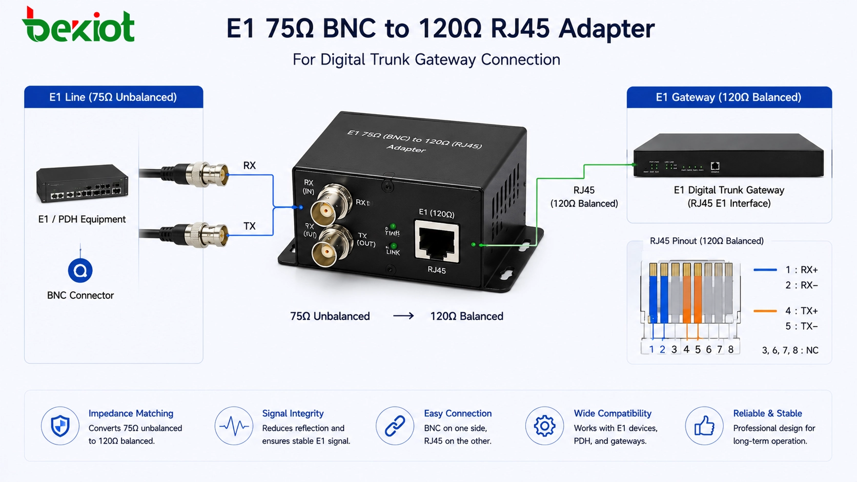
Using 75-Ohm to 120-Ohm Conversion
In real projects, it is common to encounter mismatched E1 interfaces. For example, the carrier may provide a 75-ohm BNC E1 line, while the E1 gateway or PBX trunk card may use a 120-ohm RJ45 interface. This does not mean the devices cannot be connected, but an impedance conversion solution is required.
A 75-ohm to 120-ohm adapter or conversion cable can be used to bridge the two physical interface types. One side connects to the 75-ohm BNC coaxial line, and the other side connects to the 120-ohm twisted-pair RJ45 interface. The TX/RX relationship should still follow the same rule: transmit connects to receive, and receive connects to transmit.
This type of adapter is especially useful during PSTN trunk migration, PBX replacement, digital trunk gateway deployment, and carrier handoff changes. It allows the project team to keep the existing E1 line while connecting to equipment with a different physical interface.
Distance and Link Status Checks
Cable distance is another factor that should be checked during E1 deployment. In practical wiring guidance, both 75-ohm and 120-ohm E1 connections are usually designed within 500 meters. Most gateway-to-equipment jumper connections are much shorter than this, but distance should still be considered when E1 cables pass through equipment rooms, distribution frames, or building cabling routes.
After wiring is completed, technicians should check the E1 link indicator on the gateway or trunk card. Many devices use an alarm light to show whether the E1 layer is connected. In common designs, a red alarm light turning off may indicate that the link layer has become normal. Some devices may also show a green light when the E1 link is established.
Because indicator behavior may vary between manufacturers, engineers should refer to the device manual. However, the general troubleshooting logic is the same: if the E1 link does not come up, check interface type, impedance matching, TX/RX crossover, cable continuity, connector quality, grounding, carrier-side status, and framing or signaling configuration.
Common Problems During On-Site Wiring
| Problem | Possible Cause | Recommended Check |
|---|---|---|
| E1 link does not establish | TX and RX are not crossed correctly | Swap transmit and receive pairs or test an alternate cable |
| Interface mismatch | One side is 75-ohm BNC and the other side is 120-ohm RJ45 | Use a 75-ohm to 120-ohm adapter or conversion cable |
| Intermittent alarm | Loose connector, poor cable quality, or grounding issue | Check BNC fastening, RJ45 crimping, shielding, and ground connection |
| No voice service after link is up | Physical layer is normal but signaling or trunk configuration is wrong | Check PRI signaling, clock source, numbering, routing, and PBX configuration |
| Distance-related instability | Cable route is too long or has poor transmission quality | Keep E1 cabling within suitable distance and avoid poor intermediate joints |
A Practical Deployment Workflow
Confirm the Carrier Handoff
Before making cables, confirm what the carrier or upstream device provides. The project team should check whether the handoff is 120-ohm RJ45, 75-ohm BNC, or another form delivered through a distribution frame. This step avoids unnecessary cabling changes later.
Identify the Gateway Interface
Check the E1 gateway or PBX trunk card interface type. If the gateway uses RJ45 but the carrier provides BNC, prepare a proper adapter in advance. If both sides use RJ45, confirm the pin definition. If both sides use BNC, confirm which connector is TX and which is RX.
Build the Cable Around Signal Direction
Do not wire E1 only by connector shape. Always confirm the transmit and receive direction. For 120-ohm RJ45 wiring, pay attention to pins 1, 2, 4, and 5. For 75-ohm BNC wiring, connect the receive port to the opposite transmit port and the transmit port to the opposite receive port.
Check the Link Before Dial Plan Testing
The E1 link layer should be normal before SIP trunk rules, number routing, inbound routing, outbound routing, or call testing begins. If the physical E1 layer is not stable, upper-layer configuration will be difficult to verify.
Record the Final Wiring Standard
After the project is commissioned, label the cables and document the final wiring method. This should include interface type, pin sequence, TX/RX direction, adapter usage, carrier handoff location, and gateway port number. Good documentation reduces future maintenance risk.
Solution Value in Modern Voice Networks
Although SIP trunking is widely used today, E1 digital trunk access is still important in many voice projects. Some organizations still use carrier E1 lines, legacy PBX systems, or digital trunk resources for reliability, numbering continuity, or existing telecom contracts. An E1 trunk gateway allows these resources to be integrated into newer IP-based communication systems.
With an E1 gateway, legacy PSTN trunk lines can be connected to an IPPBX, unified communication system, call center platform, dispatch platform, or voice recording system. This helps protect existing telecom investment while enabling SIP-based routing, centralized management, and flexible system expansion.
For system integrators, correct E1 wiring is not just a small installation step. It determines whether the digital trunk layer can establish a stable connection. Once the physical layer is correct, later work such as clock selection, signaling configuration, number planning, route control, and call testing can proceed more smoothly.
Final Takeaway
E1 digital trunk gateway wiring mainly depends on two physical interface types: 120-ohm balanced RJ45 and 75-ohm unbalanced BNC. A typical E1 telephone trunk can carry 30 voice channels, making it suitable for larger projects that need centralized PSTN access and unified number resources.
For 120-ohm RJ45 wiring, the commonly used pins are 1, 2, 4, and 5, with pins 1 and 2 used for receive and pins 4 and 5 used for transmit. For 75-ohm BNC wiring, one connector is used for receive and the other for transmit. In both cases, the key rule is that the local receive side should connect to the remote transmit side, and the local transmit side should connect to the remote receive side.
When 75-ohm and 120-ohm interfaces need to be connected, an adapter or conversion cable should be used. Cable distance should generally stay within 500 meters, and link indicators should be checked before upper-layer voice configuration. A stable E1 connection provides the foundation for reliable PSTN-to-IP voice integration.
FAQ
Is an E1 RJ45 port the same as an Ethernet port?
No. The connector may look similar, but an E1 RJ45 interface is not an Ethernet network port. It uses specific pins for transmit and receive pairs and carries digital trunk signals instead of Ethernet data.
Can a 75-ohm E1 line connect directly to a 120-ohm E1 port?
It should not be connected directly without proper conversion. A 75-ohm to 120-ohm adapter or conversion cable should be used to match the physical interface and impedance requirements.
What should be checked if the E1 alarm light stays on?
Check whether TX and RX are crossed correctly, whether the interface type matches, whether the connector is properly crimped or fastened, whether the carrier line is active, and whether the gateway port is configured correctly.
Does E1 wiring determine the telephone numbers?
No. Wiring only establishes the physical trunk connection. Telephone numbers, inbound routing, outbound routing, signaling type, and call rules are configured separately in the gateway, PBX, or IPPBX system.
Why is documentation important after E1 commissioning?
E1 wiring may involve custom cables, adapters, distribution frames, and carrier handoff points. Clear documentation helps future engineers troubleshoot faster and prevents accidental changes to TX/RX direction or interface matching.