General Purpose Input/Output, commonly abbreviated as GPIO, is a flexible digital interface used by processors, controllers, embedded boards, industrial equipment, security devices, and communication systems to sense external conditions or control external actions. A GPIO pin can often be configured by software as either an input or an output, allowing the same platform to support buttons, sensors, relays, alarms, indicators, door contacts, reset signals, and many simple control tasks.
Although GPIO appears simple compared to interfaces like Ethernet, USB, RS‑485, and CAN, it plays a critical role in real‑world systems. It gives equipment a direct way to link physical events to software logic: a door opens, a fault contact changes, a relay energises, an alarm beacon lights, or a controller receives an emergency signal. This article explains how GPIO works, its functions, and the value it brings in practical design.
The basic meaning of GPIO
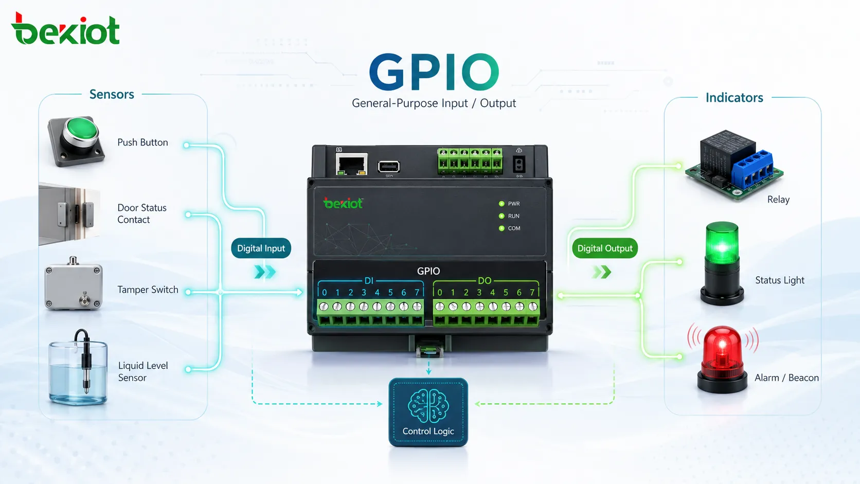
GPIO refers to a digital pin or terminal that is not permanently assigned to a single fixed function. System designers and software developers can configure it according to the needs of a project. On a microcontroller it appears as small pins on the chip; in industrial equipment it appears as terminals labelled DI, DO, I/O, alarm input, relay output, trigger input, or dry contact interface.
The term “general purpose” is important because it means the same physical interface can support many different external connections, provided the electrical requirements match. A GPIO input might read a button in one product design, while in another it detects a tamper switch, a liquid level sensor, or a door status contact.
How GPIO works inside a device
Input mode
When a GPIO pin is configured as an input, the device reads the electrical state of the pin. In most digital circuits, the state is interpreted as HIGH or LOW. Depending on the circuit design, HIGH may mean an active signal, a closed contact, or a detected voltage level, while LOW may mean an inactive signal or an open contact.
Input mode is commonly used for buttons, magnetic door contacts, motion detectors, alarm contacts, limit switches, emergency stop feeds, sensor outputs, and monitoring signals. To avoid floating or unstable readings, input circuits often use pull‑up or pull‑down resistors, which establish a known default state when no external contact is driving the signal.
Output mode
When a GPIO pin is configured as an output, the device drives the pin to a defined digital state. This output can be used to control an LED, activate a buzzer, energise a relay, reset another circuit, enable a module, or send a simple control signal to a connected device.
In real installations, a GPIO output rarely drives a large load directly. Instead, it often controls a transistor, optocoupler, relay module, solid‑state relay, or driver circuit. This protects the controller and allows the GPIO signal to switch higher‑voltage or higher‑current equipment such as sirens, locks, signal lamps, gate motors, and external alarm devices.
Software configuration
GPIO behaviour is normally defined by software or firmware. Developers can set the direction, initial state, interrupt behaviour, debounce, polarity, pull‑up or pull‑down mode, and sometimes alternative pin functions. This flexibility allows a single hardware platform to adapt to different products or project requirements.
Some systems expose GPIO settings through a web interface, configuration file, device management platform, or API. In this case, the installer can link a physical input to an event rule such as “door forced open”, “fault input active”, or “alarm reset button pressed” without rewriting low‑level firmware.
Key functions of GPIO
The value of GPIO lies in turning simple physical conditions into events that software understands, and turning software decisions into physical actions. In many systems, it is the smallest and most direct interface between the equipment and its surrounding environment.
| GPIO function | Typical signal type | Common use |
|---|---|---|
| Digital input detection | HIGH/LOW, open/closed, active/inactive | Reading buttons, door contacts, fault contacts, sensor outputs, alarm triggers |
| Digital output control | On/off control signal | Activating relays, indicators, buzzers, locks, reset lines, external modules |
| Interrupt‑driven operation | Rising edge, falling edge, level change | Fast response to emergency inputs, tamper events, limit switches, sensor changes |
| Status feedback | Equipment ready, alarm active, fault condition | Informing a controller of device health, link status, relay position, or process state |
| Interlock logic | Permission or inhibition signal | Preventing unsafe actions until required conditions are confirmed |
Beyond simple on/off control, GPIO can support event‑driven workflows. An input change can trigger a software interrupt directly instead of waiting for periodic polling. This is important in safety monitoring, access control, alarm notification, industrial equipment protection, and emergency response.
Why GPIO adds system value
Connects digital systems to physical events
Many modern systems rely on software platforms, IP networks, cloud dashboards, and data interfaces. However, real sites still contain doors, buttons, sensors, relays, sirens, gates, cabinets, pumps, and machines. GPIO helps connect these physical elements to the digital control layer without forcing every device to support a complex protocol.
This makes GPIO very useful in modernisation projects. An old contact output from an alarm panel, access controller, machine unit, or environmental sensor can often be wired to a GPIO input, allowing new software systems to monitor legacy equipment without replacing everything at once.
Simplifies control and event logic
For many tasks, GPIO is more efficient than a full data protocol. If a device only needs to know whether a contact is open or closed, a GPIO input can be faster, cheaper, and easier to maintain than a serial or network integration. Likewise, if a system only needs to turn a relay on or off, a GPIO output provides a direct and clear control path.
Simplicity does not mean low value. In many critical environments, clear binary logic is preferred because it is easy to test, document, and troubleshoot. A technician can measure contact status with a multimeter, verify relay activation, and isolate wiring problems quickly.
Improves integration flexibility
GPIO allows a single device to participate in multiple systems. A controller can receive alarm inputs from sensors, output triggers to a public address system, activate warning lights, send equipment status to a monitoring platform, or coordinate with access equipment. This flexibility reduces the need for dedicated hardware in every project.
In scalable systems, GPIO can be part of a multi‑layer integration. Simple field signals enter through GPIO, then become software events, network messages, dashboard alerts, logs, or automated workflows. A simple electrical state is transformed into a traceable operational event.
Electrical and design considerations
Voltage level and current capacity
One of the most important GPIO design checks is electrical compatibility. Many embedded GPIO pins operate at 3.3 V or 5 V logic levels, while industrial field signals may use 12 V, 24 V, or dry relay contacts. Connecting incompatible voltages directly can damage the device.
Designers often use interface circuits, optocouplers, level shifters, relay modules, or industrial I/O boards to separate sensitive electronics from field wiring. For outputs, current capacity must be carefully checked; a pin that can drive a small LED may not be able to drive a relay coil, lock, siren, or motor input without a driver circuit.
Signal polarity and default state
GPIO logic can be active‑high or active‑low. In an active‑high design, HIGH means the event is active; in an active‑low design, LOW means the event is active. Because both methods are common, polarity must be confirmed during configuration and commissioning.
The default state is also important. Some alarm and safety designs prefer normally‑closed circuits because a broken wire or disconnected cable can be detected as an abnormal condition. Other designs use normally‑open circuits for simple activation. The right choice depends on safety requirements, monitoring needs, and device capabilities.
Noise protection and debounce
Mechanical contacts can bounce when opening or closing, producing rapid transitions that the software might read as multiple events. Debounce logic filters these transitions by requiring the signal to remain stable for a defined period before it is accepted.
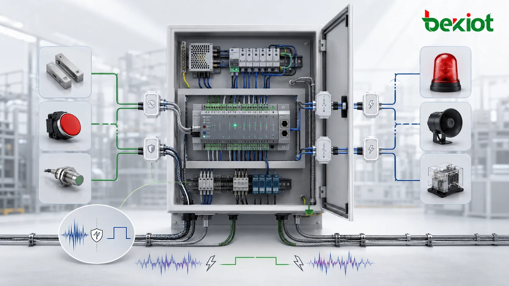
Long cables, industrial environments, motors, power supplies, and electromagnetic interference can also add noise. In harsh installations, shielded cables, proper grounding, surge protection, isolation, and input filtering may be needed. GPIO must be treated as part of the wiring design, not only as a software setting.
Typical GPIO applications
Access control and security systems
GPIO is widely used in access control and security systems. Inputs can detect door status, request‑to‑exit buttons, tamper switches, emergency release signals, motion detector outputs, or intrusion alarm contacts. Outputs can activate locks, sirens, strobe lights, relays, or alarm panels.
In integrated security platforms, a GPIO input can become an event that triggers video recording, sends a notification, changes door state, or displays a camera view. This makes GPIO useful even when the main system is IP‑based, because many field devices still provide reliable contact inputs and relay outputs.
Industrial automation and machinery
Industrial systems use GPIO for limit switches, machine status feedback, start/stop commands, fault signals, interlocks, signal towers, conveyor sensors, and control panel buttons. Simple digital I/O remains popular because it is robust, easy to inspect, and compatible with many controllers.
GPIO can support local control logic or link equipment to a higher‑level monitoring system. For example, a machine fault output can be wired to a gateway input and then forwarded to a maintenance dashboard or alarm notification system.
Embedded devices and IoT products
GPIO is one of the most common interfaces in embedded system development. It allows small devices to interact with LEDs, buttons, sensors, relays, displays, expansion modules, wake‑up signals, and power control circuits. Developers use it in prototypes and finished products alike.
In IoT systems, GPIO turns physical inputs into connected events. A water leak sensor, cabinet door switch, vibration alarm, or emergency button can enter through digital pins before the firmware processes it and sends it over the network.
Building systems and utility equipment
Utility systems use GPIO‑like interfaces for HVAC status, generator alarms, UPS faults, fire alarm relays, elevator signals, gate control, lighting activation, and environmental monitoring. These signals help building operators coordinate safety, energy management, and operational response.
Because many building devices come from different vendors and generations, GPIO provides a practical common denominator. It may not offer detailed data like a full protocol, but it reliably transmits important binary conditions such as alarm active, fault present, equipment running, or door open.
Communication and emergency devices
Communication terminals, paging controllers, intercoms, gateways, emergency phones, and routing equipment may use GPIO for alarm inputs, call triggers, relay outputs, external buttons, warning lights, door release, or status feedback. This allows voice communication, visual notification, and physical control to work together.
For instance, pressing an emergency button can activate a GPIO input, start a call, energise a relay, and notify a monitoring platform. A relay output can control a local beacon, siren, gate, or external recording system. These flows are useful in industrial sites, campuses, transport facilities, and public safety environments.
Comparing GPIO with other interfaces
GPIO should not be confused with communication protocols. It does not carry structured messages like Ethernet, Modbus, CAN, RS‑485, USB, or SIP. Instead, it typically represents simple digital states. This makes it easy to use but limited in the amount of information it can convey.
If a system needs detailed data, diagnostics, addressing, authentication, or multi‑device communication, a protocol‑based interface is usually more suitable. When the task is simply to detect a basic event or provide on/off control, GPIO is often more direct and less expensive. Many systems use both together: GPIO for local physical actuation, and network protocols for management, logging, and remote operation.
Best practices for using GPIO
Define event logic before wiring
Before connecting cables, designers should define what each input and output means. A clear I/O list should include the signal name, direction, voltage level, active state, normal state, connected device, cable route, and expected software action. This helps avoid confusion during installation and maintenance.
It is also helpful to map GPIO events to operational workflows. A door contact input should not simply be labelled “DI1”; it should be documented as “Equipment room door status” with clear behaviour for normal open, forced open, alarm delay, logging, and notification.
Use isolation when reliability matters
Isolation protects sensitive electronics from voltage spikes, ground loops, wiring faults, and external equipment issues. In industrial, outdoor, access control, and emergency environments, isolated inputs and relay outputs are often a safer choice than direct GPIO connections.
When long cable runs are present, installers should consider surge protection, cable shielding, grounding strategy, and separation from high‑voltage or high‑current cables. These practices reduce false triggering and protect the device over the long term.
Test every condition during commissioning
GPIO commissioning should include the normal state, active state, cable‑disconnect behaviour, alarm reset, recovery after power loss, and software event logging. It is not enough to confirm that the signal works once; the system should be tested under realistic operating conditions.
For safety‑related functions, tests should also confirm fail‑safe or fail‑secure behaviour. If a power loss, broken cable, or device reboot occurs, the system should enter the intended state and generate a clear log for maintenance or alarm when needed.
Conclusion
GPIO is a simple but powerful interface that allows electronic systems to detect physical events and control external actions. It supports digital inputs, digital outputs, relays, contacts, alarms, indicators, interlocks, and many practical integration flows. From embedded products and IoT devices to access control, industrial automation, building systems, and emergency communications, GPIO remains a useful way to connect software logic with real‑world conditions.
The best GPIO designs go beyond pin assignment. They require correct voltage matching, clear signal logic, reliable wiring, isolation, documentation, and thorough testing. When designed properly, GPIO makes systems faster to respond, more flexible, easier to maintain, and easier to integrate in mixed‑equipment environments.
Frequently Asked Questions
Can GPIO be used over long cable distances?
GPIO can be used over cable runs, but the distance depends on voltage level, cable quality, noise environment, input design, and protection method. For long distances or harsh environments, isolated I/O modules, shielded cable, surge protection, or protocol‑based remote I/O may be more reliable than a direct connection.
What is the difference between GPIO and a relay contact?
GPIO is usually an electronic digital input or output on a controller, while a relay contact is a mechanical or solid‑state switching interface that is electrically isolated. A relay can help a low‑power GPIO output control a higher‑power or electrically separate circuit.
Why might a GPIO input trigger falsely sometimes?
False triggering can be caused by contact bounce, floating inputs, poor grounding, electrical noise, long unshielded cables, incorrect pull‑up or pull‑down settings, or voltage level mismatches. Debounce filters and proper wiring design usually reduce these problems.
Should GPIO settings be documented after installation?
Yes. Every input and output should be documented with the connected device, active state, normal state, voltage level, cable label, software rule, and test result. Good documentation makes troubleshooting, expansion, and device replacement much easier.
Can GPIO replace a full communication protocol?
GPIO can replace a protocol only when the information is simple, such as on/off, open/closed, alarm/normal, or enable/disable. If a system needs detailed values, commands, device addressing, diagnostics, or security features, a communication protocol is usually required.