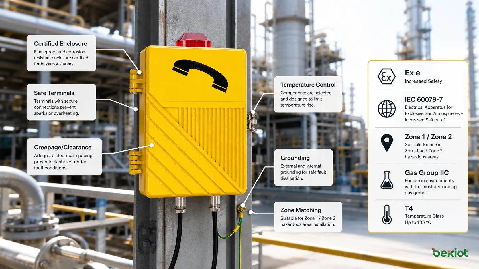
In hazardous gas environments, a safe electrical device is not defined by a rugged shell alone. The equipment must prevent ignition-capable conditions such as sparks, arcs, unsafe temperature rise, loose terminals, insulation failure, or unsuitable cable entries under the certified conditions of use.
This technical encyclopedia article explains Increased Safety, or Ex e, from the viewpoint of protection-level standards. It discusses Ex eb and Ex ec selection, zone matching, gas groups, temperature class, terminal safety, creepage and clearance, enclosure ratings such as IP66, cable glands, earthing, marking interpretation, inspection, and the difference between Ex e and other explosion-protection methods. It also lightly references the Becke Telcom EX-BH621 explosion-proof amplified telephone as an example of a hazardous-area communication endpoint with IP66 enclosure protection.
Core Safety Philosophy
The central idea is that some electrical equipment can be made safe for explosive atmospheres by increasing its electrical and mechanical safety margins. The design avoids parts that normally produce sparks or arcs, controls temperature rise, strengthens insulation, improves terminal reliability, and prevents looseness or tracking that could become an ignition source.
This approach is suitable for equipment whose normal operation does not require open sparking contacts or hot ignition-capable surfaces. For example, terminal connections, certain enclosures, lighting assemblies, and selected electrical components can be designed under this principle. If the equipment normally generates arcs or sparks, another protection method, such as flameproof, intrinsic safety, encapsulation, pressurization, or another suitable technique, may be required.
The word “increased” is important. It does not mean ordinary electrical design with a label added later. It means the design must provide additional safeguards beyond normal industrial equipment requirements so that the probability of ignition is reduced to an acceptable level for the certified protection category.
Standards Framework Behind the Marking
The most commonly referenced international framework for hazardous-area electrical equipment is the IEC 60079 series. General explosion-protected equipment requirements are usually associated with IEC 60079-0, while the specific design, construction, testing, and marking requirements for increased safety are associated with IEC 60079-7. In European markets, ATEX regulatory requirements and harmonized EN standards are also relevant. In many international projects, IECEx certification is used as a recognized conformity assessment route.
The framework does not evaluate only one feature. It looks at the complete equipment design, materials, electrical clearances, terminals, temperature behavior, enclosure construction, marking, documentation, routine tests, and manufacturing control. This is why a hazardous-area device cannot be judged only by appearance, enclosure thickness, or a waterproof rating.
Correct use also requires installation standards and site rules. Even certified equipment can become unsafe if cable glands, wiring methods, earthing, sealing, maintenance, or zone selection are wrong. Certification and installation must work together.
Protection Levels: eb and ec
Modern increased-safety marking commonly uses levels such as Ex eb and Ex ec. The level indicates the degree of protection and the intended Equipment Protection Level. In many gas atmosphere applications, Ex eb is associated with a higher level of protection suitable for Zone 1 conditions when all other marking details match the site. Ex ec is generally associated with a lower level of protection suitable for Zone 2 conditions when properly selected.
This distinction matters because hazardous areas are classified according to how likely an explosive atmosphere is to be present. A Zone 1 area has a higher probability of explosive gas presence than a Zone 2 area. Therefore, the equipment protection level must match the risk level of the location.
Selection should never be made from the letters “Ex e” alone. The complete marking must be reviewed, including the protection level, equipment group, gas group, temperature class, ambient temperature range, certificate conditions, and any special installation notes.
Zone Matching and Risk Alignment
Hazardous area zoning is based on the likelihood and duration of explosive atmosphere presence. Equipment selection must match this classification. A product suitable for a less hazardous zone cannot automatically be used in a more hazardous zone.
In practical projects, engineers compare the area classification drawing with the equipment certificate and marking. They verify whether the device is intended for gas or dust atmospheres, whether it matches the required zone, whether the gas group is suitable, and whether the temperature class is safe for the ignition temperature of the surrounding atmosphere.
This step is critical because an otherwise certified product may still be unsuitable for a particular site. Explosion protection is always application-specific.
Gas Group Requirements
Gas groups classify explosive atmospheres according to ignition characteristics. Equipment marked for a more demanding gas group may be suitable for less demanding groups, but the reverse is not automatically true. Common gas group markings include IIA, IIB, and IIC for gas atmospheres, with IIC representing more severe gases such as hydrogen-related atmospheres.
The design of Ex e equipment must account for the gas group through clearances, creepage distances, insulation behavior, enclosure properties, and ignition risk control. The gas group on the equipment marking should be checked against the site’s hazardous material classification.
If the site atmosphere is not clearly known, equipment selection becomes risky. The process safety documentation, area classification report, and material data should guide the choice.
Temperature Class Control
Temperature classification is one of the strictest protection requirements. Equipment installed in explosive atmospheres must not reach a surface temperature that could ignite the surrounding gas or vapor. The marking may show a temperature class such as T1, T2, T3, T4, T5, or T6, or a specific maximum surface temperature depending on the application.
The equipment must be assessed under specified operating conditions and ambient temperature limits. Heat sources may include electrical losses, terminal resistance, enclosure heating, internal components, sunlight, external process heat, and poor ventilation.
Temperature class should not be treated as a decorative marking. If the site gas has a low ignition temperature, a device with a higher allowed surface temperature may be unsafe even if the device is otherwise certified.
Electrical Spacing and Insulation
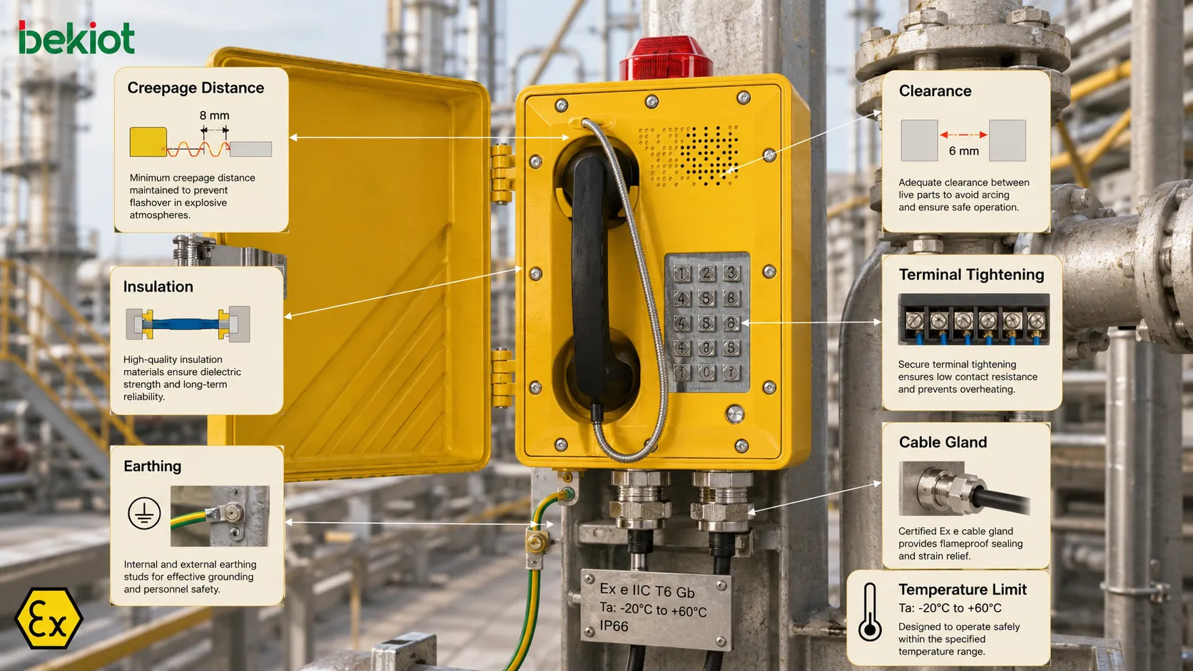
Clearance and creepage distance are important design requirements. Clearance refers to the shortest distance through air between conductive parts, while creepage refers to the distance along the surface of an insulating material. In hazardous locations, insufficient spacing can increase the risk of tracking, flashover, or insulation failure.
Ex e design therefore requires controlled spacing according to voltage, pollution conditions, material group, and protection level. The goal is to prevent electrical faults from producing arcs, sparks, or hot tracks under the expected operating environment.
Insulation materials must also be suitable for thermal, mechanical, and environmental stress. A material that performs well in a normal indoor environment may not be acceptable in a hot, humid, corrosive, or contaminated hazardous area.
Terminal and Connection Safety
Loose electrical connections are dangerous because they can create heat, arcing, voltage drop, or intermittent contact. Increased-safety equipment places strong emphasis on terminals and conductors. The connection method must maintain reliable contact under vibration, temperature cycling, installation handling, and long-term service conditions.
Terminal blocks, screws, clamps, spring terminals, conductor sizes, torque values, and wiring methods must follow the certified design and installation instructions. If a terminal is tightened incorrectly or a conductor is outside the permitted range, the safety basis may be compromised.
Maintenance teams should not replace terminals, glands, or internal connection components with ordinary parts unless the certification documentation permits it. Small component changes can invalidate the protection concept.
Enclosure Protection and Environmental Resistance
Enclosures protect internal components from dust, water, mechanical damage, corrosion, accidental contact, and environmental exposure. For hazardous-area equipment, enclosure design must support both electrical safety and explosion protection requirements.
Ingress protection ratings such as IP66 are often used to describe resistance against dust and powerful water jets. This rating is important in outdoor, dusty, wet, offshore, washdown, and industrial environments. However, IP rating is not the same as explosion protection. It is a supporting enclosure characteristic, not a substitute for Ex certification.
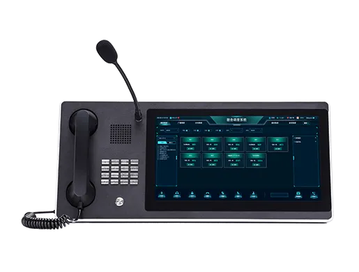
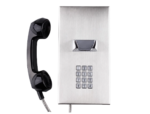
For communication or public-address points in hazardous areas, the EX-BH621 explosion-proof amplified telephone from Becke Telcom can be considered as an example of a rugged field communication endpoint; its IP66 enclosure protection helps resist dust and powerful water jets, while final suitability still depends on the project’s hazardous-area classification, certificate marking, gas group, temperature class, cable entry method, and installation rules.
Mechanical Strength and Impact Protection
Hazardous-area equipment may be installed in places where mechanical impact, vibration, corrosion, dust, rain, chemical exposure, or temperature variation is common. The enclosure, cover, fasteners, cable entries, hinges, windows, gaskets, and mounting points must remain safe under realistic operating conditions.
Mechanical weakness can indirectly create ignition risk. A cracked enclosure may allow contamination. A damaged cable gland may reduce ingress protection. A loose cover may change the certified construction. A broken terminal support may reduce electrical spacing.
Therefore, mechanical inspection is part of safety management. Explosion protection should be maintained throughout the equipment lifecycle, not only at the time of purchase.
Marking and Certificate Interpretation
Equipment marking provides essential information for selection and installation. A typical hazardous-area marking may include the Ex symbol, protection concept, equipment group, category or protection level, gas group, temperature class, ambient range, certificate number, and special condition symbols.
The installer should read the complete marking rather than focusing on only one item. For example, “Ex eb IIC T4 Gb” contains information about protection type, gas group, temperature class, and equipment protection level. If any part does not match the site requirement, the equipment may not be suitable.
Certificate numbers and special conditions should also be reviewed. Some certificates include an “X” suffix, which means special conditions for safe use must be followed. These conditions may involve ambient temperature limits, cable glands, mounting position, cleaning methods, or electrostatic precautions.
Comparison of Key Selection Factors
| Selection Factor | What It Controls | Why It Matters |
|---|---|---|
| Protection Level | Ex eb, Ex ec and related EPL suitability | Matches the equipment to the hazardous zone risk. |
| Gas Group | IIA, IIB, IIC gas atmosphere compatibility | Ensures the device is suitable for the ignition characteristics of the gas. |
| Temperature Class | Maximum permitted surface temperature | Prevents equipment surfaces from becoming ignition sources. |
| Ingress Rating | Dust and water resistance of the enclosure | Supports environmental reliability but does not replace Ex certification. |
| Installation Method | Cable entries, earthing, glands, wiring, torque | Maintains certified protection after field installation. |
Routine and Type Testing
Explosion-protected equipment is not only designed on paper. It must be tested and assessed according to applicable standards and certification procedures. Testing may involve dielectric strength, temperature rise, mechanical construction, enclosure properties, terminal behavior, impact resistance, thermal endurance, marking durability, and other requirements depending on the product type.
Some tests are type tests performed during certification, while some may be routine tests performed during production. Manufacturing quality control is important because certified design must be consistently reproduced.
Users should recognize that field modification can undermine tested performance. Drilling extra holes, changing cable entries, replacing certified components, repainting with unsuitable coatings, or altering internal wiring can affect compliance.
Cable Entries and Glands
Cable entry selection is a common source of installation errors. Cable glands, plugs, adapters, reducers, and sealing components must be suitable for the protection method, enclosure type, cable type, gas group, temperature range, and environmental conditions.
Incorrect glands can reduce ingress protection, damage cables, compromise earth continuity, or invalidate the certified construction. Unused entries must be closed with suitable certified stopping plugs.
Installers should follow the equipment instructions and local hazardous-area installation standards. A certified enclosure with an unsuitable cable entry may not provide the intended safety level.
Earthing and Bonding
Protective earthing and equipotential bonding help reduce electric shock risk, static accumulation, fault voltage, and ignition risk related to fault currents. Ex e equipment often includes internal and external earth connection points that must be used correctly.
Connections should be clean, secure, corrosion-resistant, and mechanically protected. In outdoor or corrosive environments, periodic inspection is necessary because loose or corroded earth connections can create hidden risk.
Earthing should be designed as part of the site electrical system rather than treated as an afterthought during final installation.
Static Electricity and Surface Materials
Some hazardous-area risks come from electrostatic charging. Non-metallic enclosure parts, coatings, labels, viewing windows, plastic components, or cleaning methods can contribute to static accumulation under certain conditions.
Equipment documentation may include warnings about cleaning with a damp cloth, avoiding dry rubbing, or preventing surface charge buildup. These warnings are part of safe use and should not be ignored.
In dusty, dry, or high-flow environments, electrostatic precautions can be especially important.
Installation Discipline
Installation quality is as important as product selection. The installer must verify zone classification, equipment marking, cable entry method, wiring, torque, sealing, earthing, environmental exposure, and mechanical mounting.
The equipment should not be installed outside its ambient temperature range or in a gas group beyond its marking. Covers should be tightened according to instructions. Gaskets and seals should remain clean and correctly seated. Cable bends should not place stress on entries.
After installation, inspection should confirm that the equipment has not been damaged and that the final installed condition matches the certified arrangement.
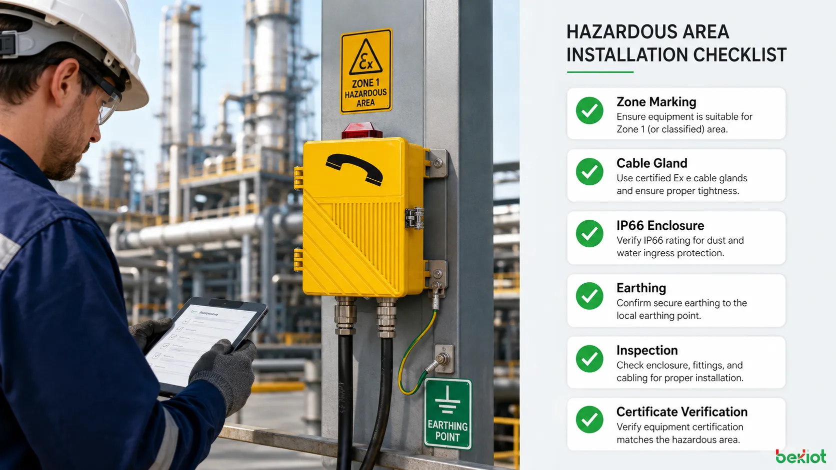
Inspection and Maintenance Rules
Hazardous-area inspection should be planned regularly. Maintenance teams should check enclosure integrity, fasteners, cable entries, gaskets, corrosion, terminal tightness, insulation condition, earth continuity, marking readability, unauthorized modification, and environmental damage.
Inspection intervals should reflect site risk. Harsh environments, vibration, offshore salt exposure, chemical corrosion, dust accumulation, frequent washdown, and high temperature may require more frequent inspection than clean indoor locations.
Repairs should follow certified repair procedures. If a part is damaged, replacement should use approved components and methods. Uncontrolled repair can destroy the protection basis even if the equipment appears to work electrically.
Difference From Flameproof and Intrinsic Safety
Flameproof protection focuses on containing an internal explosion and preventing flame transmission to the external atmosphere. Increased safety focuses on avoiding ignition sources through safer construction, spacing, terminals, insulation, and temperature control. Intrinsic safety limits energy so that sparks and thermal effects cannot ignite the atmosphere under defined conditions.
These methods solve the hazard in different ways. One contains, one prevents, and one limits energy. They are not interchangeable without engineering review.
Many complex products may use more than one protection concept. For example, one part may be flameproof while another terminal chamber uses increased safety. The complete marking and certificate explain the actual protection arrangement.
Common Misunderstandings
A frequent misunderstanding is that Ex e means the equipment is explosion-proof in the same way as a flameproof enclosure. This is not accurate. Increased safety equipment is designed to prevent ignition sources under its certified conditions rather than contain an explosion.
Another misunderstanding is that a high IP rating automatically means hazardous-area suitability. IP66 can support environmental protection, but it does not prove explosion protection by itself.
A third misunderstanding is that all Ex equipment can be used in all hazardous zones. The zone, protection level, gas group, temperature class, and certificate conditions must be checked together.
A fourth misunderstanding is that wiring changes are minor. In Ex e equipment, terminals, spacing, glands, conductor size, and torque are part of the safety design. Improper field wiring can create risk.
Application Scenarios
Increased-safety equipment is often found in process plants, chemical production, oil storage, gas compression areas, refineries, offshore facilities, fuel depots, hazardous warehouses, power distribution zones, and industrial communication points. It is useful where equipment must operate reliably without creating sparks or excessive heat under specified conditions.
For communication systems, hazardous-area endpoints may need to support voice calling, paging, emergency contact, alarm notification, or public-address functions while resisting dust, water, corrosion, and mechanical stress. The communication function should not be evaluated separately from explosion protection; both must be suitable for the site.
In field selection, engineers should compare not only communication features but also the certification marking, environmental rating, cable entry arrangement, mounting condition, and maintenance accessibility.
Documentation and User Responsibility
Correct protection level use depends on documents. The certificate, instruction manual, marking label, area classification report, installation drawing, inspection record, and maintenance procedure all work together. If any document is missing, the safety decision becomes weaker.
End users are responsible for installing and maintaining equipment according to its intended use. Certification does not remove the need for site assessment. A certified device installed in the wrong zone, with wrong glands, or outside its temperature range may be unsafe.
For procurement teams, the safest approach is to request complete technical documents before purchase and verify them with engineering, safety, and maintenance personnel.
Practical Selection Checklist
Start by confirming whether the area is classified as gas, dust, or both. Then verify the zone, gas group, temperature class, ambient temperature range, equipment protection level, and required ingress protection.
Next, confirm that the equipment marking and certificate match the site. Review special conditions for safe use. Check cable entry requirements, mounting method, earthing, and environmental exposure.
Finally, confirm that the maintenance team can inspect and service the equipment without unauthorized modification. If replacement parts, glands, seals, or covers are difficult to obtain, long-term compliance may become harder.
Engineering Value
The value of Ex e protection is that it allows suitable electrical equipment to be used in hazardous areas by controlling ignition risk through disciplined design and construction. It supports practical industrial operation where electrical terminals, lighting, motors, communication devices, and control components are necessary.
Its strict standards create consistency. Engineers can compare marking, certificate data, protection levels, gas groups, and temperature classes instead of relying on vague descriptions such as heavy-duty or weatherproof.
The protection concept is effective only when the product, installation, and maintenance remain aligned with the certified conditions. This is why hazardous-area engineering must always treat equipment selection as part of a complete safety system.
Increased Safety (Ex e) adheres to strict protection-level standards by preventing ignition sources through controlled construction, secure terminals, safe spacing, temperature limitation, certified marking, and disciplined installation rather than by relying on enclosure strength alone.
FAQ
Can Ex e equipment be installed in any explosive gas area?
No. It must match the site’s zone classification, equipment protection level, gas group, temperature class, ambient range, and certificate conditions.
Does IP66 mean the device is explosion-protected?
No. IP66 describes dust-tight and powerful water-jet resistance. Explosion protection requires appropriate Ex certification and correct hazardous-area marking.
Why are terminal connections so important?
Loose or unsuitable terminals can create heat, arcing, or intermittent contact. Ex e design relies heavily on secure and certified connection methods.
Can users drill extra cable holes in an Ex e enclosure?
Generally no unless the certificate and manufacturer instructions specifically permit it. Unapproved modification can invalidate the protection concept.
What should be checked during maintenance?
Check marking readability, enclosure condition, gaskets, cable glands, terminal tightness, corrosion, earthing, unauthorized changes, and compliance with the original installation requirements.