Induced EMF is the electrical effect that makes generators produce voltage, transformers transfer energy, sensors detect motion, and many electromagnetic systems convert movement or changing fields into usable signals.
The Core Idea Behind Electromagnetic Induction
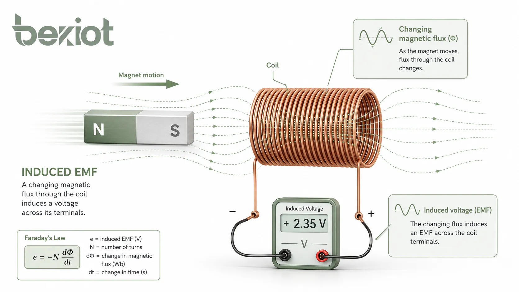
Induced EMF, or induced electromotive force, is the voltage generated in a conductor or coil when the magnetic flux linked with it changes. The word “force” in electromotive force does not mean mechanical force. In electrical engineering and physics, EMF refers to the energy supplied per unit charge, and it is measured in volts.
The basic principle is simple: when a conductor experiences a changing magnetic field, or when it moves through a magnetic field in a way that cuts magnetic field lines, a voltage is produced. If the circuit is closed, that voltage can drive current. If the circuit is open, the voltage may still exist between terminals, but current cannot continuously flow.
Changing Magnetic Flux
Magnetic flux describes how much magnetic field passes through a given area. If the magnetic field strength changes, the area changes, the angle changes, or the conductor moves relative to the field, the magnetic flux linked with the circuit changes.
This changing flux is the direct reason induced EMF appears. A coil with many turns can produce a larger induced voltage because each turn links with the changing magnetic flux, and the effects add together.
Faraday’s Law in One Sentence
Faraday’s law states that the induced EMF in a circuit is proportional to the rate of change of magnetic flux linkage. Faster flux change produces higher induced voltage. More coil turns also increase the induced voltage.
This is why generators use rotating coils or rotating magnetic fields, transformers use alternating magnetic flux, and inductive sensors detect movement or position through magnetic field variation.
How Induced EMF Is Generated
There are two common ways to generate induced EMF. The first is by changing the magnetic field around a stationary conductor or coil. The second is by moving a conductor through a magnetic field so that it cuts magnetic field lines.
Both methods follow the same electromagnetic induction principle. What changes is the physical source of the flux variation. In transformers, the magnetic field changes with alternating current. In generators, mechanical motion changes the flux linkage.
By Changing the Magnetic Field
If a coil is placed near a magnetic field that increases or decreases over time, the magnetic flux through the coil changes. This changing flux induces voltage in the coil. The coil itself does not need to move.
This principle is used in transformers, inductors, wireless charging coils, current transformers, electromagnetic pickups, and many sensing devices. In these systems, the changing field is usually produced by alternating current or a time-varying magnetic source.
By Moving a Conductor Through a Magnetic Field
When a conductor moves through a magnetic field, free charges inside the conductor experience magnetic force. This separates charges along the conductor and creates a voltage difference. This is called motional EMF.
The induced voltage depends on the magnetic field strength, conductor length, moving speed, and the angle between the conductor’s motion and the magnetic field. Maximum EMF is produced when the conductor cuts the magnetic field lines at a right angle.
By Rotating a Coil in a Magnetic Field
A generator commonly uses rotational motion. As the coil rotates inside a magnetic field, the angle between the coil area and the magnetic field changes continuously. This creates a changing magnetic flux and produces alternating EMF.
The faster the coil rotates, the faster the magnetic flux changes. This increases the generated voltage and frequency, depending on the generator design. This is the foundation of many alternators and AC generators.
The Role of Lenz’s Law
Lenz’s law explains the direction of induced EMF and induced current. It states that the induced current flows in a direction that opposes the change in magnetic flux that caused it. This is why the negative sign appears in Faraday’s law.
The opposition described by Lenz’s law is not an accident. It reflects energy conservation. If the induced current supported the original change instead of opposing it, the system could create energy without input, which would violate physical principles.
Why the Direction Matters
Direction is important in motors, generators, relays, transformers, inductive braking, and protection circuits. If a coil produces EMF in the wrong direction relative to the system design, the circuit may not operate as intended.
In practical wiring, polarity marks, winding direction, terminal labels, and phase relationships all matter. Engineers must understand the direction of induced EMF when connecting coils, transformers, generators, and sensors.
Back EMF in Motors
When a motor rotates, its windings move through a magnetic field and generate an induced voltage that opposes the supply voltage. This is called back EMF. It limits current during normal operation and is an important part of motor behavior.
At startup, motor speed is low, so back EMF is low. This can allow high starting current. As the motor speeds up, back EMF increases and reduces the net voltage driving current through the winding.
Main Formulas for Calculation
Induced EMF can be calculated in different ways depending on the physical situation. The most general formula is Faraday’s law. For a straight conductor moving through a magnetic field, the motional EMF formula is often more convenient.
Before calculating, identify whether the problem involves a changing magnetic flux through a coil, a conductor moving in a magnetic field, or a rotating coil. Then select the formula that matches the situation.
Faraday’s Law for a Coil
The general formula is:
ε = -N × ΔΦ / Δt
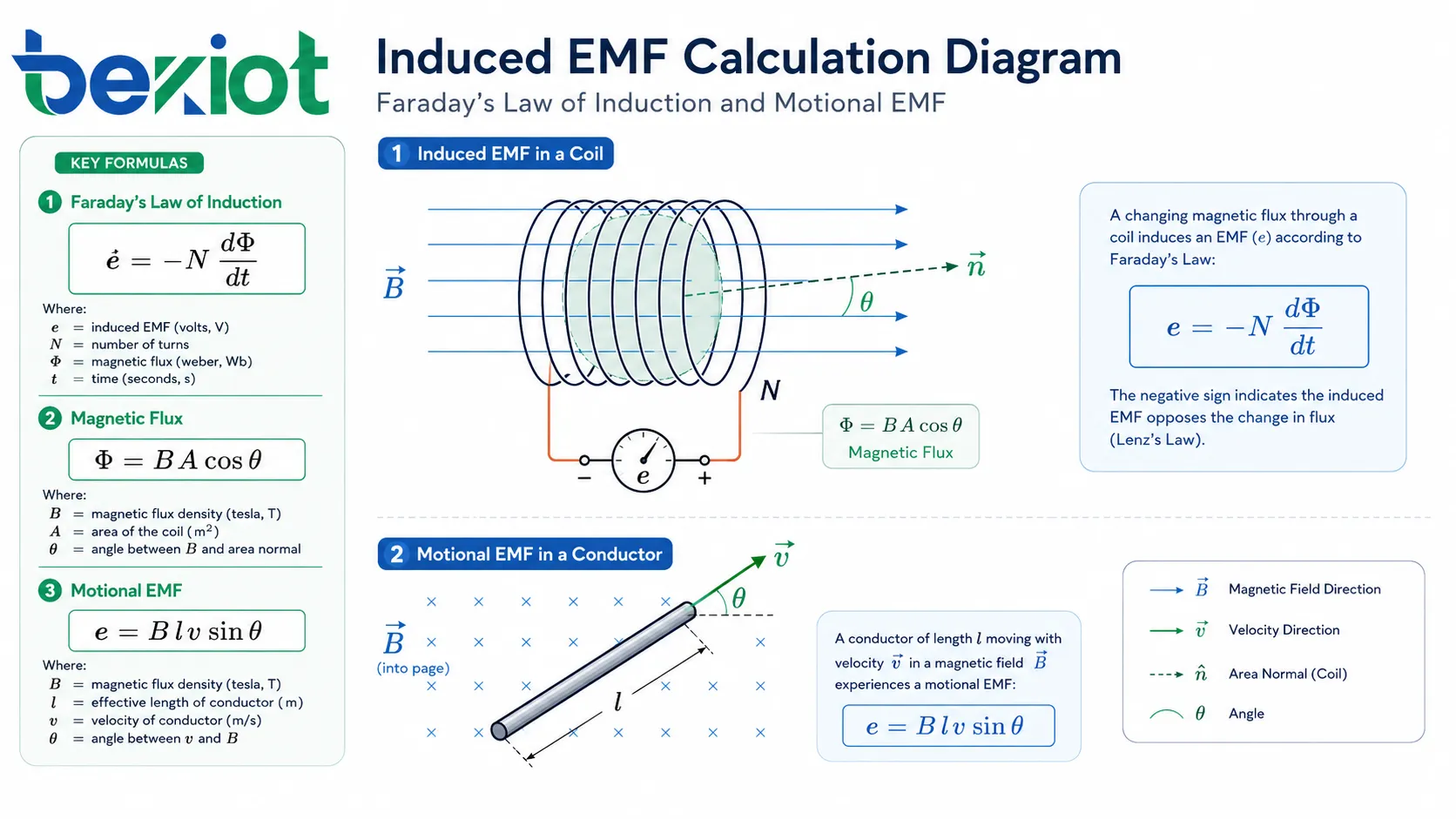
In this formula, ε is the induced EMF in volts, N is the number of turns in the coil, ΔΦ is the change in magnetic flux in webers, and Δt is the time interval in seconds. The negative sign represents Lenz’s law and indicates that the induced EMF opposes the change in flux.
For many practical calculations, the magnitude is used:
|ε| = N × |ΔΦ| / Δt
Magnetic Flux Formula
Magnetic flux is calculated as:
Φ = B × A × cosθ
Here, Φ is magnetic flux in webers, B is magnetic flux density in teslas, A is the area in square meters, and θ is the angle between the magnetic field and the normal line perpendicular to the coil area.
If the magnetic field is perpendicular to the coil surface, the flux is maximum. If the magnetic field is parallel to the coil surface, the flux is zero because no field passes through the loop area.
Motional EMF Formula
For a straight conductor moving through a magnetic field, the common formula is:
ε = B × l × v × sinθ
In this formula, B is magnetic flux density in teslas, l is the effective conductor length in meters, v is velocity in meters per second, and θ is the angle between the motion and the magnetic field. If the conductor moves perpendicular to the field, sinθ = 1, and the formula becomes ε = B × l × v.
| Symbol | Meaning | Common Unit |
|---|---|---|
| ε | Induced electromotive force | Volt, V |
| N | Number of coil turns | Turns |
| Φ | Magnetic flux | Weber, Wb |
| B | Magnetic flux density | Tesla, T |
| A | Area linked by magnetic field | Square meter, m² |
| l | Effective conductor length | Meter, m |
| v | Conductor velocity | Meter per second, m/s |
| t | Time | Second, s |
Step-by-Step Calculation Examples
Calculation becomes easier when the physical process is clearly identified. The first example uses Faraday’s law for a coil. The second example uses the motional EMF formula for a moving conductor.
Example One: Coil with Changing Magnetic Flux
A coil has 200 turns. The magnetic flux through each turn changes from 0.06 Wb to 0.02 Wb in 0.5 seconds. What is the average induced EMF?
The flux change is:
ΔΦ = 0.02 - 0.06 = -0.04 Wb
The magnitude of the change is 0.04 Wb. Using Faraday’s law:
|ε| = N × |ΔΦ| / Δt = 200 × 0.04 / 0.5 = 16 V
The average induced EMF is 16 volts. The actual polarity depends on the direction of the flux change and the winding direction, as described by Lenz’s law.
Example Two: Moving Conductor in a Magnetic Field
A straight conductor with an effective length of 0.5 m moves at 3 m/s through a magnetic field of 0.8 T. The motion is perpendicular to the magnetic field. What is the induced EMF?
Because the conductor moves perpendicular to the field, sinθ = 1. The calculation is:
ε = B × l × v = 0.8 × 0.5 × 3 = 1.2 V
The induced EMF is 1.2 volts. If the conductor moved at an angle instead of perpendicular to the field, the result would be lower because the sinθ factor would be less than 1.
Example Three: Flux from Field, Area, and Angle
A coil has an area of 0.02 m² and is placed in a magnetic field of 0.5 T. The magnetic field is perpendicular to the coil surface. What is the magnetic flux through the coil?
When the field is perpendicular to the coil surface, the angle between the magnetic field and the area normal is 0 degrees, so cos0° = 1. The flux is:
Φ = B × A × cosθ = 0.5 × 0.02 × 1 = 0.01 Wb
If this flux later changes, the induced EMF can be calculated by applying Faraday’s law to the change in flux over time.
Factors That Affect Induced Voltage
Induced EMF is affected by several physical and design factors. Understanding these factors helps engineers design generators, transformers, sensors, inductive devices, and electromagnetic systems with predictable output.
Rate of Flux Change
The faster the magnetic flux changes, the greater the induced EMF. This is why a rapidly moving magnet can produce a larger voltage than a slowly moving magnet in the same coil.
In AC systems, frequency affects induced voltage because higher frequency causes magnetic flux to change more quickly. This is important in transformers, alternators, inductive power transfer, and electromagnetic sensing.
Number of Turns
A coil with more turns produces a higher induced EMF when the same flux change passes through each turn. This is why transformers and generators often use many turns of wire to reach the desired voltage.
However, more turns also increase resistance, size, capacitance, and sometimes losses. Practical design must balance voltage output, current capacity, temperature rise, insulation, and physical space.
Magnetic Field Strength
A stronger magnetic field can produce more magnetic flux and therefore more induced EMF, assuming other factors remain the same. Stronger magnets, better magnetic cores, and optimized air gaps can improve induction performance.
Magnetic materials also matter. A suitable iron or ferrite core can concentrate magnetic flux, but saturation, hysteresis, and eddy current losses must be considered in practical equipment.
Area and Orientation
The area of the loop and its orientation relative to the magnetic field affect magnetic flux. A larger loop can capture more flux. A loop aligned for maximum flux will produce a stronger change when the field varies.
In rotating machines, the changing angle between the coil and magnetic field is what produces alternating EMF. In sensors, careful placement and orientation can improve signal strength and accuracy.
Applications in Electrical and Electronic Systems
Induced EMF is a foundation of many electrical technologies. It is not limited to classroom physics. It appears in power generation, energy conversion, signal detection, motion sensing, wireless power, protection systems, and electromagnetic compatibility analysis.
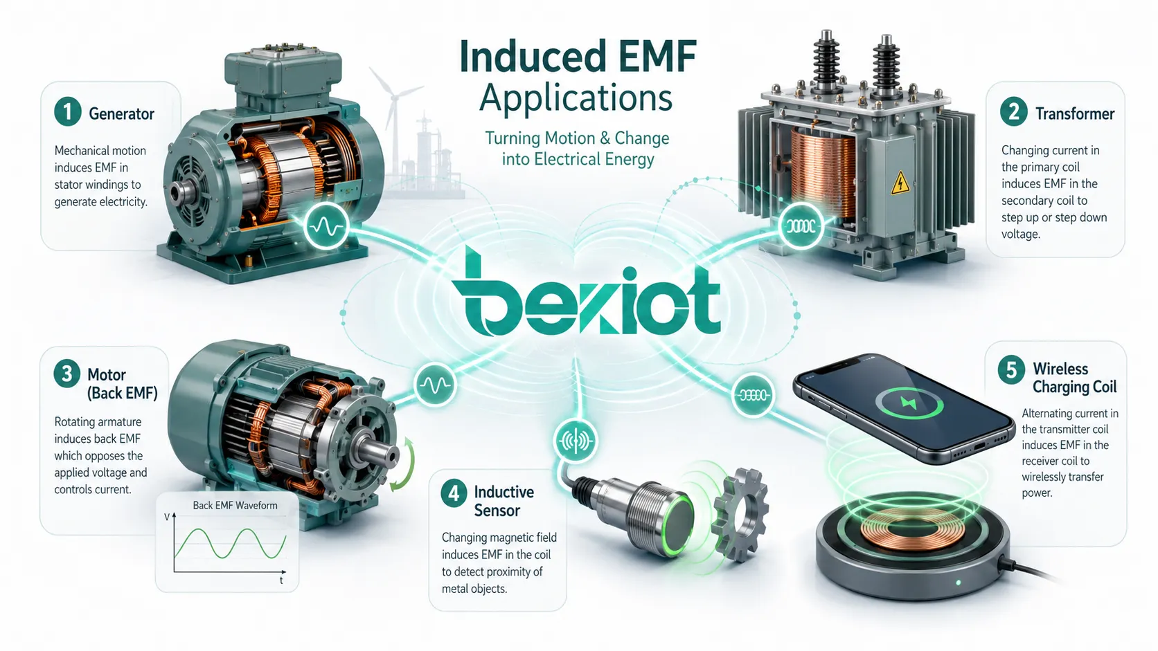
Generators and Alternators
Generators convert mechanical energy into electrical energy through electromagnetic induction. A conductor or coil moves relative to a magnetic field, creating changing flux linkage and producing EMF.
In large power stations, turbines rotate generator rotors to produce electrical output. In smaller systems, alternators in vehicles, portable generators, and bicycle dynamos use the same basic principle at different scales.
Transformers and Power Conversion
Transformers use induced EMF to transfer energy between windings through a changing magnetic field. Alternating current in the primary winding creates changing flux in the core, which induces voltage in the secondary winding.
The voltage ratio depends mainly on the turns ratio between the primary and secondary windings. This makes transformers essential for power distribution, chargers, adapters, isolation circuits, audio systems, and industrial equipment.
Motors and Back EMF
Electric motors generate back EMF while rotating. This induced voltage opposes the applied supply voltage and affects motor current, speed regulation, efficiency, and control behavior.
Motor drives often use back EMF information for control, especially in brushless DC motors and sensorless control systems. Understanding back EMF helps engineers design safer and more efficient motor systems.
Sensors and Measurement Devices
Inductive sensors, magnetic pickups, current transformers, tachometers, metal detectors, and some flow meters rely on induced EMF. These devices convert motion, position, current, or magnetic change into an electrical signal.
Because induced voltage depends on motion and field change, such sensors are often useful in non-contact measurement, rotating machinery monitoring, speed detection, and industrial automation.
Wireless Charging and Inductive Power Transfer
Wireless charging uses changing magnetic fields to induce voltage in a receiving coil. A transmitter coil creates an alternating magnetic field, and a receiver coil converts part of that changing flux into electrical energy.
Efficiency depends on coil alignment, distance, frequency, magnetic design, load condition, and control electronics. Poor alignment or excessive distance can reduce induced voltage and increase losses.
Practical Design and Measurement Notes
In real systems, induced EMF is affected by non-ideal conditions. Resistance, leakage flux, core losses, eddy currents, capacitance, temperature, load current, waveform shape, and mechanical tolerances can all influence the measured voltage.
Open-Circuit and Loaded Voltage
The induced EMF calculated from Faraday’s law often represents the generated voltage before considering internal drops and load effects. When a load is connected, current flows and the terminal voltage may be lower than the open-circuit EMF.
This is common in generators, transformers, batteries, and sensors. Engineers must distinguish between generated EMF and actual terminal voltage under operating load.
Eddy Currents and Losses
Changing magnetic fields can induce circulating currents in conductive materials. These are called eddy currents. They can cause heating and energy loss in transformer cores, motor cores, generator laminations, and nearby metal structures.
To reduce eddy current losses, magnetic cores are often laminated or made from materials with higher electrical resistance. Ferrite cores are also used in high-frequency applications because they reduce certain loss mechanisms.
Measurement with Instruments
Induced EMF can be measured with a voltmeter, oscilloscope, data acquisition system, or specialized analyzer. The correct instrument depends on signal level, frequency, waveform, source impedance, and whether the voltage is steady, pulsed, or alternating.
For fast-changing signals, an oscilloscope is often more useful than a simple multimeter because it shows waveform shape, peak value, timing, and transient behavior. For sinusoidal AC, RMS voltage is commonly used.
Common Mistakes When Calculating
Many errors in induced EMF calculation come from mixing up flux, magnetic field, area, and angle. Another common mistake is ignoring the number of turns in a coil or using the wrong time interval for flux change.
Using Field Strength Instead of Flux
Faraday’s law uses magnetic flux, not only magnetic field strength. If the problem gives magnetic flux density, area, and angle, calculate flux first using Φ = B × A × cosθ.
Only after flux is known can the change in flux over time be used to calculate induced EMF. Skipping this step can lead to incorrect units and wrong results.
Ignoring Direction and Polarity
If the question asks only for magnitude, the negative sign in Faraday’s law may be omitted. If the question asks for direction or polarity, Lenz’s law must be considered.
Direction depends on the magnetic field direction, coil winding direction, motion direction, and whether flux is increasing or decreasing. Diagrams are often necessary for accurate polarity analysis.
Confusing Peak, Average, and RMS Values
AC induced EMF may be described as peak voltage, average voltage, or RMS voltage. These are not the same. RMS is commonly used for practical AC power calculations, while peak values are often used in waveform analysis.
When comparing generator, transformer, or sensor specifications, always check which voltage value is being stated and under what operating conditions.
FAQ
What is induced EMF?
Induced EMF is the voltage generated in a conductor or coil when the magnetic flux linked with it changes. It can be produced by a changing magnetic field, a moving conductor, or a rotating coil in a magnetic field.
What law is used to calculate induced EMF?
Faraday’s law is used to calculate induced EMF. The common formula is ε = -N × ΔΦ / Δt, where N is the number of coil turns, ΔΦ is the change in magnetic flux, and Δt is the time interval.
Why is there a negative sign in Faraday’s law?
The negative sign represents Lenz’s law. It shows that the induced EMF acts in a direction that opposes the change in magnetic flux that caused it. This reflects conservation of energy.
How is motional EMF calculated?
Motional EMF is commonly calculated with ε = B × l × v × sinθ. If the conductor moves perpendicular to the magnetic field, the formula becomes ε = B × l × v.
Does induced EMF always create current?
No. Induced EMF creates a voltage. Current flows only if there is a closed conducting path. In an open circuit, voltage may be present across terminals, but continuous current cannot flow.
Where is induced EMF used in real systems?
Induced EMF is used in generators, alternators, transformers, motors, inductive sensors, current transformers, wireless charging systems, magnetic pickups, and many electromagnetic measurement devices.