A Simple Interface Behind Many Control Signals
Passive dry contact is a voltage-free contact interface that changes between open and closed states without supplying electrical power from the contact itself. It is commonly used in alarm systems, sensors, relays, PLCs, building automation, access control, fire alarm interfaces, HVAC equipment, industrial monitoring, and remote I/O systems.
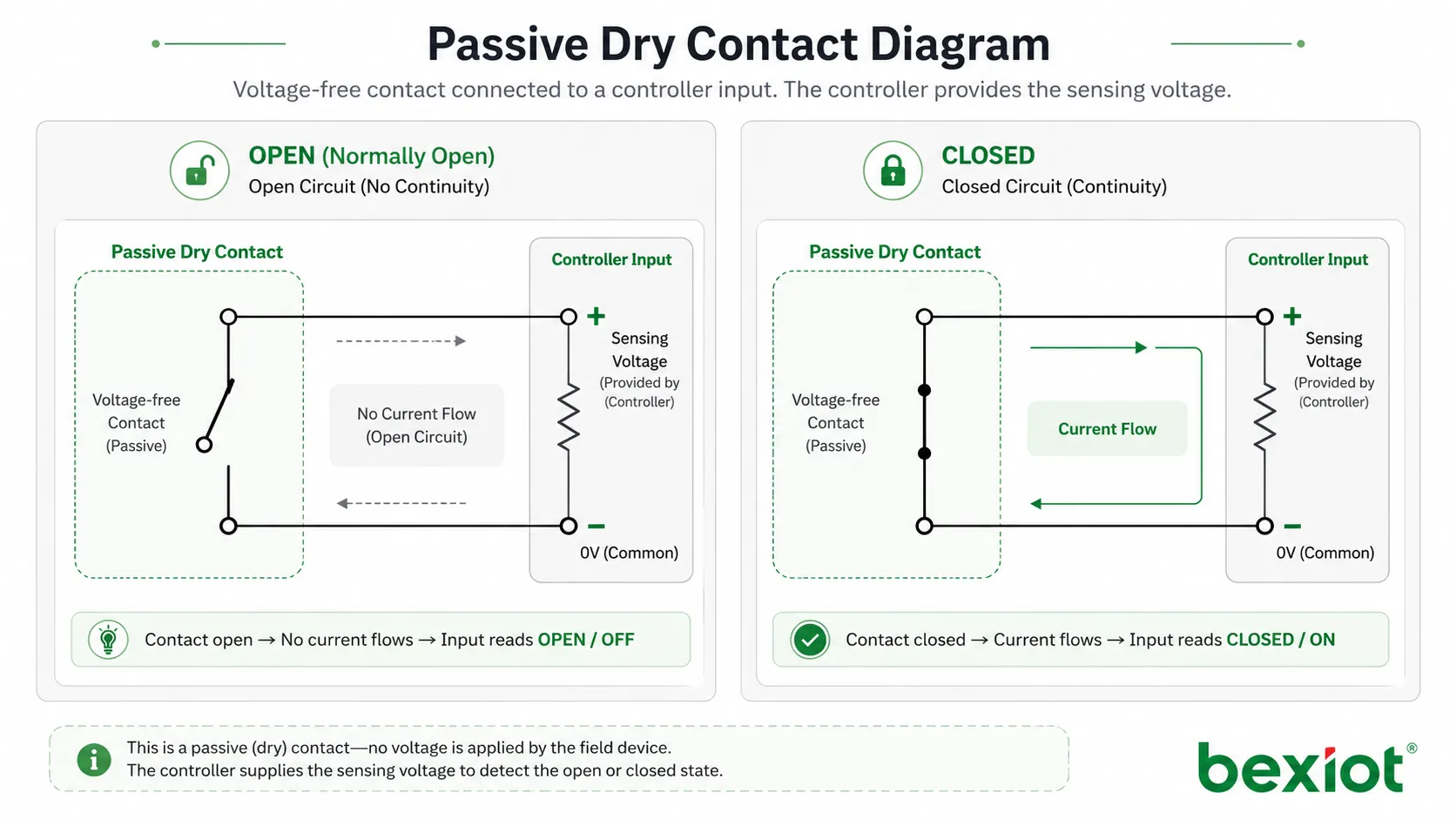
The word “passive” means the contact does not actively generate a voltage signal. Instead, it behaves like a switch. The receiving device provides the sensing voltage or detection circuit, while the passive dry contact simply opens or closes to indicate status.
A passive dry contact does not send power. It only changes state, allowing another system to detect whether a circuit is open or closed.
Basic Meaning of Passive Dry Contact
A passive dry contact is typically formed by a relay contact, mechanical switch, push button, magnetic contact, limit switch, float switch, pressure switch, thermostat contact, or fault output contact. Because the contact is isolated from the power circuit, it can be connected to different control systems as long as the electrical ratings are compatible.
In practice, passive dry contacts are used when one system needs to tell another system that something has happened. For example, a door contact may close when a door is shut, a relay may close when an alarm is triggered, or a machine may open a fault contact when it enters an abnormal state.
Voltage-Free Contact
The most important characteristic is that the contact is voltage-free. It does not provide 12V, 24V, 110V, or any other active voltage output by itself. The receiving controller, alarm panel, input module, or monitoring device supplies the detection signal.
This makes passive dry contact different from an active voltage output. If an installer assumes that a passive dry contact can power a device, the circuit will not work. If external voltage is applied incorrectly to a dry-contact-only input, the receiving device may be damaged.
Open and Closed States
A passive dry contact has two basic states: open and closed. When the contact is open, the circuit is incomplete. When the contact is closed, the circuit is complete. The receiving device reads this change and interprets it as normal, alarm, fault, start, stop, enable, disable, or another configured status.
This binary behavior is simple, reliable, and easy to understand. It is one reason dry contact interfaces remain widely used even in modern digital control systems.
How It Works in a Circuit
A passive dry contact is usually wired between two input terminals of a receiving device. When the contact changes state, the receiving device detects continuity or disconnection. The external contact does not need to share the same power supply as the controller unless the system design specifically requires a common reference.
This isolation is useful because it allows different systems to exchange simple status information without directly mixing their power circuits. A fire alarm panel, access controller, BMS controller, PLC, or monitoring gateway can receive a dry contact status from another system with minimal protocol complexity.
Receiving Device Provides Sensing Power
The receiving device typically sends a small sensing current through the input circuit. When the passive dry contact closes, the circuit is completed and the input changes state. When the contact opens, the circuit is interrupted and the input changes back.
The sensing current is usually very small compared with load-driving circuits. This is why dry contacts are normally used for signaling, not for powering motors, lights, sirens, locks, or other high-load devices.
Normally Open and Normally Closed Logic
Passive dry contacts are often configured as normally open or normally closed. A normally open contact remains open in its default state and closes when an event happens. A normally closed contact remains closed in its default state and opens when an event happens.
The correct logic depends on the application. Normally open wiring is common for simple trigger events. Normally closed wiring is often preferred for monitored safety or security loops because an open circuit may indicate alarm, cable break, or device fault depending on the supervision method.
Relay Isolation
Many passive dry contacts are provided through relay outputs. A relay allows one circuit to control an isolated contact without directly connecting the control side and output side. This makes relay-based dry contacts useful for interconnecting systems from different manufacturers.
However, relay contacts still have electrical limits. The contact rating, maximum voltage, maximum current, switching frequency, and load type should be checked before connection. A dry contact suitable for signal input may not be suitable for switching a powered load.
Main Functions of Passive Dry Contact
Passive dry contact is valuable because it provides a universal and simple way to transfer status between systems. It can trigger alarms, report faults, confirm equipment states, and support automation logic without requiring complex communication protocols.
Status Reporting
Status reporting is one of the most common functions. A passive dry contact can indicate whether equipment is running, stopped, normal, faulty, open, closed, occupied, empty, enabled, disabled, or in alarm state.
For example, a pump controller may provide a dry contact output to report pump fault. A door sensor may report door open or closed state. A UPS system may report power failure, low battery, or bypass status through contact outputs.
Alarm Triggering
Passive dry contacts are widely used to trigger alarms. When a sensor or device detects an event, its relay contact changes state and the alarm panel or monitoring system receives the signal.
This method is common in intrusion alarms, fire alarm interfaces, emergency buttons, water leakage detectors, gas detection systems, temperature alarms, access control systems, and industrial safety circuits.
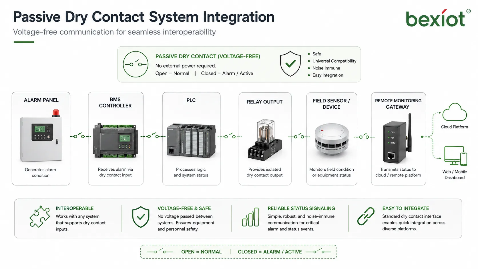
Inter-System Linkage
Many projects require linkage between systems that do not use the same communication protocol. Passive dry contact provides a practical bridge. One system only needs to open or close a contact, and the other system only needs to detect that state.
For example, a fire alarm system may send a dry contact signal to a building management system. An access control panel may send a door status signal to a security platform. A machine controller may send a fault signal to a remote monitoring gateway.
Start and Stop Control
Passive dry contacts can also be used for simple control commands. A button, relay, or controller output may close a contact to start equipment, stop equipment, reset an alarm, enable a function, or trigger a timed action.
For safety-related control, the circuit design must follow the required safety standard. A simple dry contact may not be enough for emergency stop or machine safety functions unless it is part of an approved safety circuit.
System Value in Integration Projects
The system value of passive dry contact comes from its simplicity, compatibility, and reliability. It allows different devices and systems to exchange essential status without requiring shared software protocols or deep integration.
High Compatibility
Passive dry contact works with many types of equipment because it is based on basic electrical continuity. PLCs, alarm panels, access controllers, BMS modules, I/O gateways, monitoring devices, and relay boards commonly support this interface.
This makes dry contact especially useful in retrofit projects. Older equipment that does not support modern digital protocols may still provide relay contacts that can be connected to newer monitoring platforms.
Low Integration Complexity
Dry contact integration is usually easier than protocol-based integration. Engineers do not need to write software drivers, parse data packets, manage API authentication, or configure network communication for simple state transfer.
This does not mean dry contact wiring requires no planning. Correct terminal selection, contact logic, supervision method, cable type, grounding, and documentation are still important for reliable operation.
Clear Troubleshooting
Passive dry contact circuits are relatively easy to test. Technicians can use a multimeter to check whether the contact is open or closed. They can also test whether the receiving input changes state correctly when the contact is operated.
This simplicity reduces maintenance time. If a signal fails, the technician can check the field device, contact output, cable continuity, terminal connection, and input module step by step.
Reliable Event Detection
For simple events, passive dry contact can be more direct than complex communication. A relay contact changing state is easy to detect, easy to log, and easy to connect to alarm logic.
This reliability is why dry contacts are still used in critical environments such as substations, equipment rooms, industrial plants, security systems, fire alarm interfaces, and building management systems.
Passive Dry Contact vs Wet Contact
Passive dry contact and wet contact are often compared because both are used for signal input and control wiring. The key difference is whether the field signal provides voltage.
A passive dry contact does not supply voltage. It only opens or closes. A wet contact or active signal provides voltage to the receiving input, such as 12V DC, 24V DC, or another rated voltage level.
| Item | Passive Dry Contact | Wet Contact |
|---|---|---|
| Power output | No voltage supplied by the contact itself | Voltage is supplied by the field circuit |
| Signal type | Open or closed state | Active voltage level |
| Typical examples | Relay output, switch contact, magnetic contact | 24V digital output, powered sensor output |
| Integration style | Receiving device senses continuity | Receiving device detects voltage presence |
| Main risk | Applying external voltage to a dry-only input may cause damage | Wrong voltage level or polarity may cause malfunction or damage |
Why the Difference Matters
The difference matters during wiring and commissioning. A passive dry contact input expects only contact closure or opening. If installers connect a powered output to an input that is designed only for dry contacts, the input may fail.
Similarly, a wet contact input may not detect a dry contact correctly unless the circuit is wired with the required voltage source. Always check whether the interface is dry contact, wet contact, or configurable before connecting field wiring.
Choosing the Right Interface
Use passive dry contact when simple isolated status transfer is needed. Use wet contact when the receiving system expects an active voltage signal. Some input modules support both modes through wiring options or configuration settings.
The correct choice depends on the receiving device specification, field device output type, cable distance, noise environment, safety requirements, and maintenance practice.
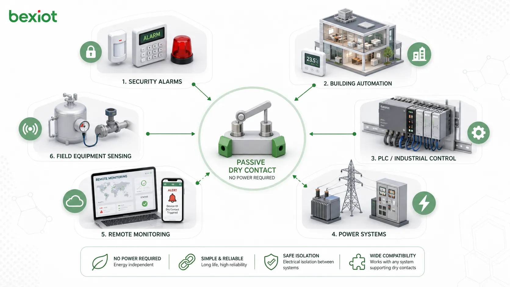
Common Application Scenarios
Passive dry contact appears in many industries because it is a simple and practical signal interface. It is especially common where systems need to exchange alarms, statuses, and trigger signals without complex data communication.
Alarm and Security Systems
Security systems use passive dry contacts for door contacts, motion detector relay outputs, panic buttons, glass break sensors, tamper switches, intrusion panels, and access control linkage.
When a contact changes state, the alarm panel or controller can identify the zone and trigger a response. The response may include siren activation, event logging, operator notification, camera linkage, or dispatch action.
Building Automation
Building automation systems use dry contacts to monitor equipment status such as fan running state, pump fault, filter alarm, elevator status, water leakage, smoke damper position, generator status, and HVAC fault output.
This allows building management platforms to collect important status signals from devices that may not support BACnet, Modbus, KNX, or other communication protocols.
Industrial Control and PLC Systems
PLC systems often receive passive dry contact signals from limit switches, pressure switches, float switches, relay outputs, emergency buttons, position contacts, and equipment fault relays.
These signals are used in automation logic, alarm handling, interlocking, machine status monitoring, and process control. Proper wiring and input filtering help improve stability in industrial environments.
Power and Energy Systems
Power equipment may provide dry contact outputs for power failure, UPS alarm, generator running, breaker trip, battery low, inverter fault, surge protection failure, and transformer temperature alarm.
Connecting these contacts to monitoring systems allows maintenance teams to detect electrical faults early and respond before service interruption becomes more serious.
Communication and Remote Monitoring
Remote monitoring gateways and communication devices often include dry contact inputs for field alarm collection. These inputs can convert simple contact signals into network messages, SMS alerts, platform alarms, or SCADA events.
This is useful for remote pump stations, equipment shelters, base stations, utility cabinets, transportation sites, unmanned rooms, and distributed infrastructure.
Installation and Wiring Considerations
Passive dry contact wiring is usually simple, but details matter. Poor wiring can cause false alarms, missed signals, intermittent faults, or equipment damage.
Confirm Contact Rating
Every contact has a rated voltage and current. Even when used for low-level signaling, the contact rating should be compatible with the receiving circuit. If the contact is used to switch higher loads, rating becomes even more important.
Signal contacts should not be used to switch loads beyond their rating. Arcing, contact wear, sticking, or failure may occur if the contact is overloaded.
Use Correct NO or NC Logic
Normally open and normally closed logic should be chosen according to the system requirement. The receiving controller must be configured to interpret the contact state correctly.
If the logic is reversed, the system may show alarm during normal operation or fail to detect a real alarm. Commissioning should include actual trigger tests instead of only visual wiring checks.
Consider Cable Distance and Interference
Long cable runs can pick up noise, especially in industrial environments near motors, drives, power cables, or high-current equipment. Shielded cable, proper routing, surge protection, and input filtering may be required.
Dry contact circuits should be separated from high-voltage wiring where required. Cable labels and terminal documentation should be clear so that maintenance teams can identify each signal later.
Use Supervised Circuits When Needed
In security and life-safety applications, supervised circuits may be used to detect not only open and closed states, but also cable break, short circuit, or tamper conditions. This is often done with end-of-line resistors.
Supervision design must match the alarm panel or input module specification. Incorrect resistor values or wiring methods can create false faults or prevent proper alarm detection.
Common Mistakes to Avoid
One common mistake is assuming that every contact input is the same. Dry contact input, wet contact input, analog input, and digital communication input are different interface types. They should not be wired without checking the device manual.
Another mistake is treating passive dry contact as a power output. A dry contact cannot power another device by itself. It only completes or interrupts a circuit supplied by the receiving side or a properly designed external circuit.
A third mistake is failing to document the logic. If future technicians do not know whether a signal is normally open, normally closed, alarm-on-open, or alarm-on-close, troubleshooting becomes slower and more error-prone.
Testing and Maintenance Tips
Passive dry contact circuits should be tested during commissioning and inspected during maintenance. The goal is to confirm both physical contact operation and correct system interpretation.
Perform Continuity Testing
Continuity testing verifies whether the contact opens and closes as expected. A multimeter can be used to check the contact state when the field device is in normal and alarm conditions.
This test helps separate field-device problems from cable or controller problems. If the contact changes correctly but the system does not detect it, the issue may be wiring, input configuration, or controller logic.
Test the Full Alarm Path
A contact test alone is not enough. The full signal path should be tested from field trigger to receiving platform. This confirms that the alarm appears with the correct name, location, priority, and response rule.
Full-path testing is especially important for safety, security, and remote monitoring applications where the contact signal must trigger real operator action.
Inspect Terminals and Cable Condition
Loose terminals, corrosion, broken conductors, damaged insulation, moisture ingress, and poor labeling can all affect dry contact reliability. These problems may cause intermittent alarms that are difficult to trace.
Periodic inspection is recommended in outdoor, industrial, high-vibration, humid, or corrosive environments.
FAQ
Can passive dry contact be connected directly to a PLC input?
Yes, if the PLC input is designed or wired to detect dry contact closure. Some PLC inputs need an external power source or common reference, so the input module wiring diagram should always be checked before connection.
Does a passive dry contact have polarity?
The contact itself usually has no polarity because it behaves like a switch. However, the receiving input circuit may have polarity if it uses DC sensing voltage, so terminal instructions should still be followed.
Can one passive dry contact signal be shared by two systems?
It is possible in some cases, but it should be done carefully. Directly connecting two input circuits to one contact can create interaction between systems. Isolation relays or signal splitters are often safer for shared signaling.
How far can a passive dry contact cable run?
The distance depends on cable type, input circuit design, electrical noise, supervision method, and site environment. Long runs may require shielded cable, surge protection, proper routing, or a remote I/O module closer to the field device.
Why do passive dry contact alarms sometimes flicker?
Flickering alarms may be caused by loose terminals, contact bounce, vibration, unstable field devices, electrical interference, cable damage, or overly sensitive input settings. Debounce delay and physical inspection can help identify the cause.
Should passive dry contact signals be documented?
Yes. Documentation should include device name, terminal number, cable ID, contact type, normal state, alarm state, receiving input, location, and response rule. Clear records make future maintenance and troubleshooting much easier.