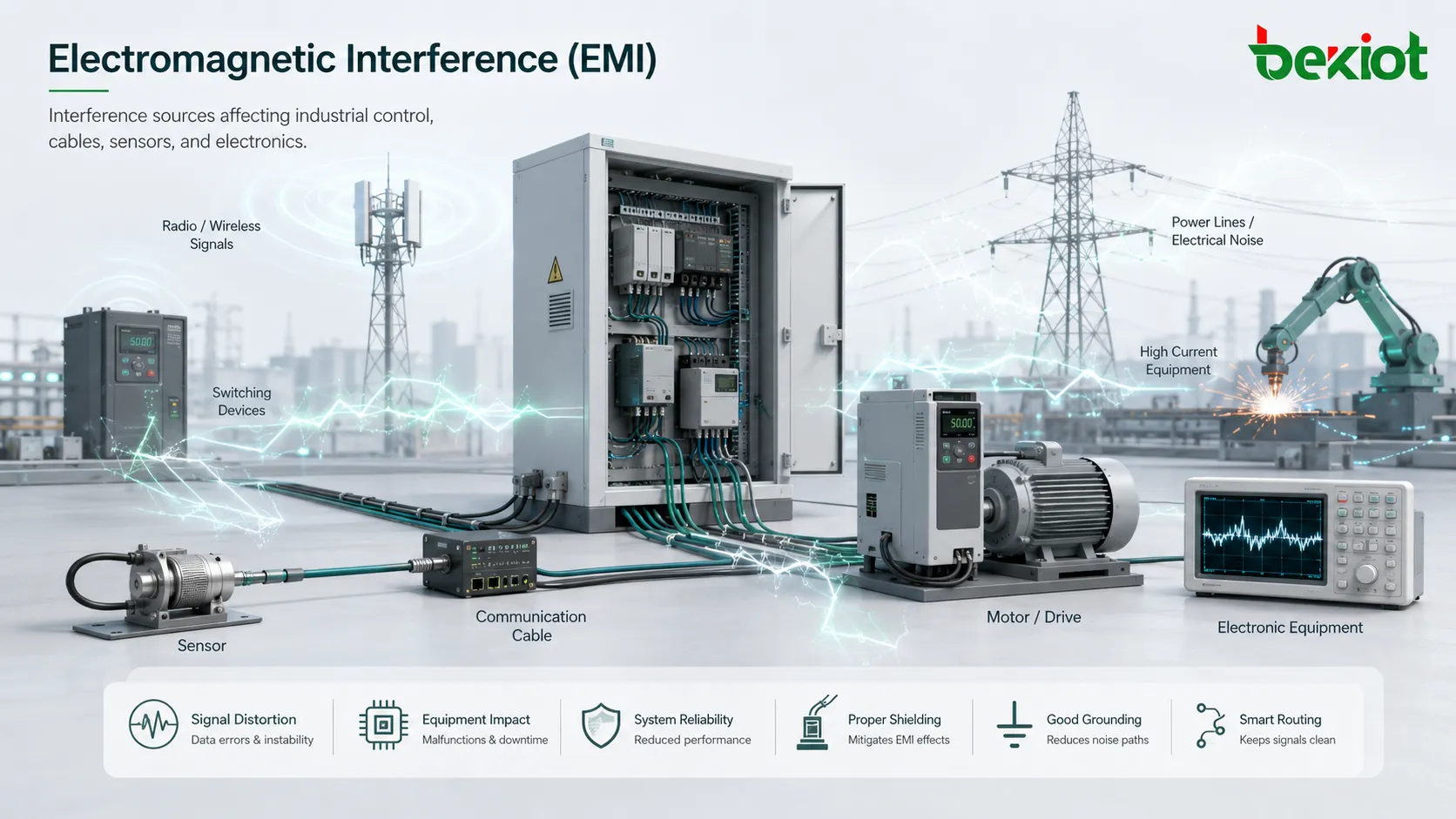
Electromagnetic interference, commonly abbreviated as EMI, is unwanted electromagnetic energy that disturbs the normal operation of electrical or electronic equipment. It may cause noise, signal distortion, communication failure, false triggering, unstable measurement, audio hum, display flicker, data errors, device reset, or complete system malfunction.
EMI can come from motors, relays, switching power supplies, radio transmitters, lightning, variable frequency drives, power lines, welding equipment, wireless devices, electrostatic discharge, poorly shielded cables, and high-speed digital circuits. In modern facilities, almost every electronic system can be both a source of interference and a victim of interference, which is why electromagnetic compatibility design is important from the earliest product and system planning stage.
Why Unwanted Signals Create Real Problems
Electronic systems are designed to process useful signals. A sensor measures voltage, a network cable carries data, a microphone captures sound, a controller sends commands, and a radio device transmits information. EMI becomes a problem when unwanted energy enters these signal paths or power paths and makes the system behave incorrectly.
The effect may be obvious or subtle. A radio may produce noise. A communication link may drop packets. A control panel may reset. A fire alarm input may trigger falsely. A medical device may show unstable readings. A production machine may stop without a clear cause. In some cases, EMI appears only when several conditions happen together, making it difficult to diagnose.
For critical systems, the risk is not only inconvenience. Interference can affect safety, uptime, data accuracy, production continuity, customer service, and regulatory compliance. This is why EMC engineering focuses on both reducing emissions from equipment and improving immunity against external disturbances.
How Interference Travels
Conducted Coupling
Conducted interference travels through physical conductors such as power cables, signal wires, grounding conductors, control lines, communication cables, or shared power supplies. A noisy device can inject unwanted voltage or current into the wiring, and that disturbance can reach another device through the same electrical path.
Common examples include switching power supply noise traveling through DC power lines, motor drive noise entering a sensor cable, or surge energy moving through a building power system. Conducted problems often require filtering, grounding review, cable separation, surge protection, and proper power distribution design.
Radiated Coupling
Radiated interference travels through space as electromagnetic fields. A cable, circuit board trace, enclosure gap, antenna, or high-speed signal path may radiate energy. Nearby equipment may receive that energy unintentionally.
Radiated issues are common with radio transmitters, wireless devices, high-frequency switching circuits, poorly shielded cables, and fast digital electronics. Solutions may include shielding, enclosure bonding, cable screening, ferrites, layout improvement, and distance separation.
Capacitive Coupling
Capacitive coupling occurs when changing voltage in one conductor creates unwanted influence on a nearby conductor through electric field interaction. This is common when signal cables run close to high-voltage or fast-switching conductors.
Increasing separation, using shielding, reducing cable parallel length, and improving grounding can help reduce capacitive coupling.
Inductive Coupling
Inductive coupling occurs when changing current in one conductor creates a magnetic field that induces voltage in another conductor. This is common near motors, transformers, high-current cables, relay coils, and power switching devices.
Twisted pairs, loop area reduction, cable routing control, shielding where appropriate, and physical separation from high-current paths can reduce this type of interference.
Common Impedance Coupling
Common impedance coupling occurs when two circuits share part of the same return path, ground conductor, or power conductor. Current from one circuit creates a voltage drop that appears as noise in another circuit.
This is why grounding and return path design matter. A shared ground is not automatically clean. Poor grounding can turn the grounding system itself into a path for interference.
EMI control is not only about adding shielding after a problem appears. It is about managing how unwanted energy is generated, coupled, transmitted, and received.
Emission and Immunity in EMC Design
Electromagnetic compatibility, or EMC, is the broader discipline that manages EMI. A compatible product should not emit excessive interference, and it should also tolerate a reasonable level of interference from its environment. This creates two major testing and design directions: emission control and immunity protection.
Emission control focuses on limiting the noise a device sends into its surroundings. This may include conducted emissions on power lines, radiated emissions from enclosures or cables, harmonic emissions, voltage fluctuations, and radio-frequency disturbance.
Immunity protection focuses on how well a device continues to operate when exposed to disturbances. This may include electrostatic discharge, radiated radio-frequency fields, electrical fast transients, surge, conducted RF, voltage dips, power interruptions, magnetic fields, and other environmental stress events.
Standards and Compliance Frameworks
IEC 61000 Series
The IEC 61000 series is one of the major EMC standard families. It includes documents related to test methods, immunity requirements, emission limits, installation environments, measurement techniques, and generic EMC requirements for different equipment categories.
Manufacturers and system designers often use relevant IEC 61000 parts to define test levels, laboratory procedures, and performance criteria. The exact parts used depend on the product type, environment, market, and applicable product-family standard.
CISPR Standards
CISPR standards focus on radio disturbance and EMC requirements for many product categories, including multimedia equipment, industrial/scientific/medical equipment, household appliances, lighting equipment, vehicles, and other devices that may generate radio-frequency interference.
For equipment that includes digital electronics, switching circuits, communication interfaces, or radio-sensitive environments, CISPR-related emission limits are often important in market access and product certification planning.
FCC Part 15
In the United States, FCC Part 15 is widely relevant for radio-frequency devices, including unintentional radiators such as many digital devices. Products may need to meet applicable emission requirements before being marketed in the U.S.
This is especially important for electronic devices containing digital logic, clock circuits, switching electronics, processors, interfaces, and communication modules. The required authorization path depends on the product and classification.
EN and CE EMC Requirements
For the European market, products may need to meet EMC requirements under applicable EU regulations and harmonized standards. Manufacturers typically use relevant EN versions of IEC or CISPR standards to demonstrate conformity for CE marking.
The selected standard should match the product category. A multimedia device, industrial controller, medical device, lighting product, or radio equipment may follow different EMC routes.
Military, Automotive, Railway, and Industry-Specific Rules
Some sectors use specialized EMC requirements. Automotive electronics, railway systems, aerospace equipment, military devices, medical products, marine equipment, and power grid systems may require additional or more severe tests than ordinary commercial products.
These environments often involve high reliability needs, strong electromagnetic fields, large motors, traction systems, radio transmitters, lightning exposure, or safety-critical operation.
| Standard Area | Main Focus | Typical Use |
|---|---|---|
| IEC 61000 | EMC test methods, immunity, emissions, and generic requirements. | Industrial equipment, electrical products, control systems, general EMC design. |
| CISPR | Radio-frequency disturbance and emission limits. | Multimedia products, appliances, lighting, ISM equipment, electronic devices. |
| FCC Part 15 | Radio-frequency device requirements in the U.S. | Digital devices, unintentional radiators, intentional radiators, consumer and business electronics. |
| EN EMC Standards | European EMC conformity through harmonized standards. | CE-marked electrical and electronic equipment. |
| Sector-Specific Standards | Special EMC requirements for high-risk environments. | Railway, automotive, military, medical, marine, aerospace, and power systems. |
Protection Ratings and Performance Levels
Unlike IP ratings for dust and water or IK ratings for impact, EMI protection is usually described through EMC test standards, test levels, emission limits, immunity performance criteria, shielding effectiveness, filter performance, surge level, ESD level, and installation category. A product should not be described only as “EMI-proof” without explaining what test or protection level was achieved.
For immunity testing, the key question is how the equipment behaves when exposed to a defined disturbance. It may continue operating normally, show temporary degradation but recover automatically, require user intervention, or suffer damage. The acceptance criterion depends on the product function and standard requirement.
For emissions testing, the key question is whether the equipment produces disturbance below the defined limit under specified conditions. Passing an emission test means the product met a limit in a defined test setup, not that it cannot interfere in any possible installation.
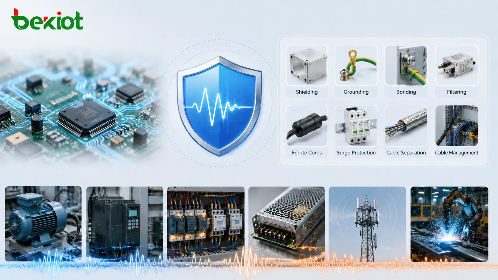
Design Methods for Reducing Interference
Shielding
Shielding uses conductive or magnetic materials to reduce electromagnetic field coupling. Metal enclosures, shielded cables, conductive gaskets, foil layers, braided screens, and shielded connector backshells can all be part of the design.
Shielding only works well when it is continuous and properly bonded. A metal box with large gaps, unbonded panels, plastic openings, or poorly terminated cable shields may perform much worse than expected.
Grounding and Bonding
Grounding and bonding provide reference paths and reduce unwanted voltage differences between equipment parts. Good bonding helps enclosure panels, cable shields, racks, and protective conductors work together as a controlled system.
Poor grounding can make interference worse. Long ground leads, loose terminals, mixed high-current and signal returns, and uncontrolled ground loops can create noise paths that are difficult to diagnose.
Filtering
Filters reduce unwanted conducted noise on power and signal lines. Common solutions include EMI filters, ferrite cores, feedthrough capacitors, common-mode chokes, LC filters, RC snubbers, and surge protection devices.
Filters should be selected according to frequency, current, voltage, impedance, and installation position. A filter placed in the wrong location may provide little benefit.
Cable Management
Cables can act as antennas or coupling paths. Routing, separation, shielding, twisting, grounding, and connector quality all affect EMC performance. Sensitive signal cables should not run closely and parallel to high-current power cables for long distances.
In industrial cabinets, separating power, control, communication, and low-level sensor wiring can significantly reduce interference problems.
PCB Layout
Many EMI issues begin on the printed circuit board. High-speed traces, switching loops, poor return paths, bad decoupling, long clock lines, and improper ground planes can create emissions or susceptibility.
Good layout practices include minimizing loop area, controlling impedance, placing decoupling capacitors close to IC power pins, separating noisy and sensitive circuits, and providing a clean return path.
Typical Sources in Real Installations
Variable Frequency Drives
Variable frequency drives control motor speed through fast switching. They are common in HVAC, pumps, conveyors, cranes, elevators, production lines, and industrial machinery. Their switching behavior can generate conducted and radiated noise.
EMI control may require shielded motor cables, output filters, proper grounding, separated cable routes, cabinet bonding, and manufacturer-recommended installation practices.
Switching Power Supplies
Switching power supplies are efficient and compact, but they can generate high-frequency noise. The noise may travel through power lines or radiate from cables and circuit boards.
Good power supply design includes input filtering, output filtering, shielding, layout control, and compliance testing under load conditions.
Relays and Solenoids
Relays, contactors, solenoids, and locks can create voltage spikes when coils are switched off. These transients may affect nearby electronics, control inputs, communication lines, or microcontrollers.
Suppression components such as flyback diodes, snubbers, MOVs, or transient voltage suppressors may be used depending on AC or DC circuit design.
Radio Transmitters
Two-way radios, cellular devices, Wi-Fi equipment, broadcast transmitters, and industrial wireless systems can expose nearby electronics to RF fields. Sensitive equipment may malfunction if it lacks sufficient immunity.
Device placement, shielding, filtering, and immunity testing help reduce the risk of radio-frequency disturbance.
Electrostatic Discharge
Electrostatic discharge occurs when static electricity suddenly transfers between objects. A user touching a keypad, connector, metal panel, or handheld device can inject a high-voltage pulse into the product.
Protection may include ESD-rated components, enclosure design, grounded surfaces, input protection, PCB layout control, and material selection.
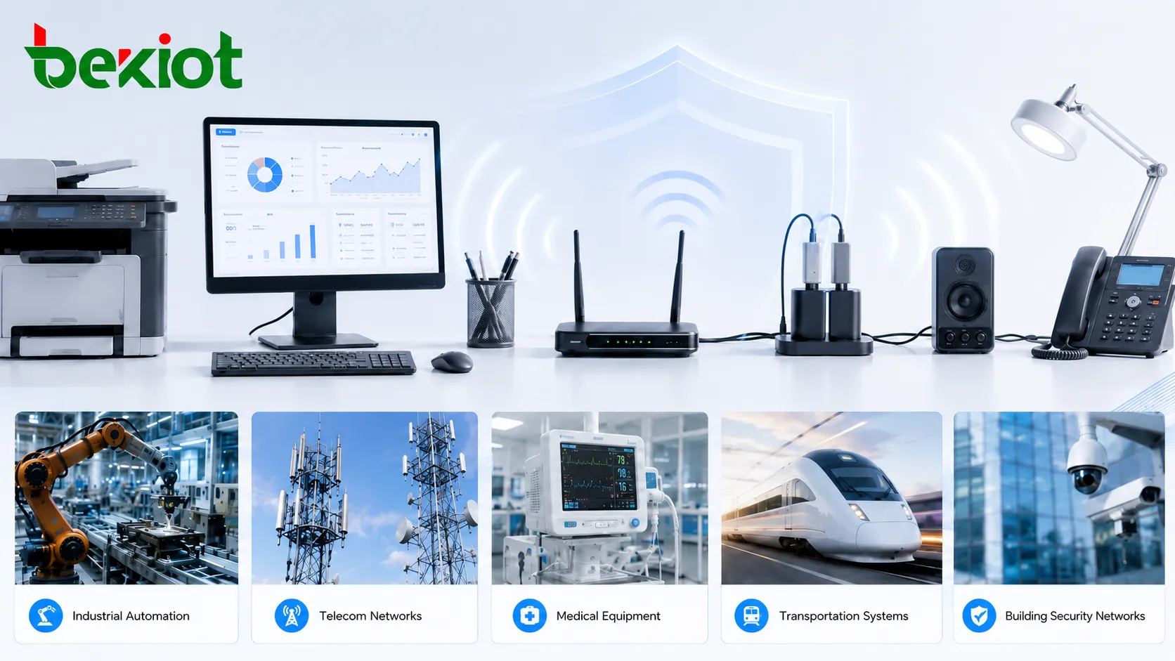
Applications Across Industries
Industrial Automation
Factories use motors, drives, sensors, PLCs, robots, power supplies, and communication networks in the same environment. EMI can cause false signals, unstable control, communication errors, and unexpected machine stops.
Industrial EMC design should include cabinet layout, cable segregation, shield termination, proper bonding, surge protection, and equipment selection suitable for noisy environments.
Telecommunications and Networking
Telecom rooms, base stations, network switches, gateways, routers, and communication terminals require stable signal performance. EMI can affect data links, voice quality, timing stability, and interface reliability.
Shielded cabling, rack bonding, clean power, surge protection, and structured grounding are important in high-availability communication systems.
Medical and Laboratory Equipment
Medical and laboratory devices often measure small signals and must operate reliably near other electronic systems. EMI may affect readings, alarms, displays, and data acquisition.
These environments require careful EMC compliance, equipment spacing, cable management, and maintenance of protective earth connections.
Transportation Systems
Railways, metro systems, vehicles, airports, ports, and tunnels contain power converters, traction equipment, communication systems, signaling equipment, lighting, cameras, and passenger information systems.
EMI protection supports safety, communication clarity, control reliability, and system availability in electrically complex environments.
Building and Security Systems
Access control, fire alarms, CCTV, intercoms, public address, elevators, HVAC controls, and building automation systems may share cable routes and power infrastructure. EMI can cause false alarms, video noise, audio hum, or communication errors.
Proper separation, shielding, grounding, surge protection, and commissioning tests help reduce these problems.
Consumer and Office Electronics
Computers, monitors, printers, chargers, routers, audio devices, lighting drivers, and office equipment must work together without unacceptable interference. EMC compliance helps protect both product usability and radio spectrum quality.
Even in ordinary offices, poor power adapters, low-quality cables, and dense electronics can create noise problems.
Testing and Measurement Process
Pre-Compliance Testing
Pre-compliance testing is often performed during product development. Engineers use near-field probes, spectrum analyzers, LISNs, test chambers, ESD simulators, surge generators, and immunity test equipment to identify problems before formal certification.
This stage helps reduce redesign cost. It is easier to fix a noisy PCB layout or weak enclosure bond before the product is fully tooled and released.
Formal Laboratory Testing
Formal testing is performed according to applicable standards and market requirements. The test setup, cable arrangement, operating mode, load condition, measurement distance, limit line, and test level must follow the selected standard.
For reliable results, the equipment under test should be operated in a representative mode. A product that passes while idle may fail when communication ports, displays, motors, relays, or processors are fully active.
Installation-Level Verification
Some EMI problems appear only after installation. A product may pass laboratory testing but still malfunction because of site wiring, grounding, nearby equipment, long cables, or poor enclosure bonding.
For complex facilities, commissioning should include site-level checks such as grounding inspection, cable routing review, surge protection verification, noise measurement, and functional testing under real operating conditions.
Common Symptoms and Troubleshooting
Intermittent Communication Failure
Data links may fail only when a motor starts, a relay switches, a radio transmits, or a nearby machine changes speed. This pattern often suggests conducted or radiated interference rather than a simple software fault.
Checking event timing, cable routing, grounding, and nearby switching equipment can help identify the source.
Audio Noise or Hum
Audio systems may pick up hum, buzz, clicking, or radio-frequency noise. Causes may include ground loops, unshielded cables, power supply noise, poor bonding, or nearby high-current wiring.
Balanced audio, proper shielding, isolation transformers, clean grounding, and cable separation can improve performance.
Unexpected Device Reset
Devices may reset because of surge, ESD, power dips, fast transients, or conducted noise. The reset may happen only during switching events or during storms.
Power filtering, transient suppression, firmware recovery design, watchdog behavior, and grounding review may be needed.
False Alarm or False Trigger
Control inputs may activate when noise is coupled into signal wiring. Long cables, high impedance inputs, poor shielding, and shared conduits with power cables can increase risk.
Input filtering, debounce logic, shielded cable, proper pull-up or pull-down design, and cable separation can reduce false triggering.
Video Distortion
Analog and digital video systems may show noise, rolling lines, dropouts, or artifacts when interference affects cables, power, or signal processing.
Shielded cables, correct grounding, clean power supplies, surge protection, and proper network design can help maintain video quality.
EMI troubleshooting is most effective when symptoms are linked to time, location, equipment state, cable path, and nearby sources of electrical activity.
Design and Installation Checklist
Start by identifying noise sources and sensitive circuits. Motors, drives, contactors, radios, switching supplies, processors, sensors, analog inputs, communication interfaces, and audio circuits should be reviewed early.
Separate noisy and sensitive cables. Power cables, motor cables, and switching lines should not share long parallel routes with sensor, audio, network, or low-voltage control cables unless proper shielding and separation are used.
Bond enclosures and cable shields correctly. A shield that is not terminated properly may fail to protect the signal and may even become a source of unwanted coupling.
Use filters and surge protection at the correct location. A power filter should be placed near the entry point. A signal protection device should match the signal type and expected disturbance level.
Test under real operating conditions. Equipment should be evaluated while loads switch, motors run, radios transmit, relays operate, and communication interfaces are active.
Maintenance and Long-Term Reliability
EMI protection can degrade over time. Loose grounding screws, corroded bonding straps, damaged cable shields, replaced power supplies, missing ferrites, altered cable routes, and cabinet modifications can change EMC performance.
Maintenance teams should inspect bonding, grounding, shielding, connectors, surge protectors, cable routes, cabinet doors, gasket continuity, and protective earth connections during periodic service.
After system changes, EMC risk should be reviewed again. Adding a new motor drive, radio system, charger, inverter, LED lighting driver, or network device may introduce new interference paths that did not exist during the original installation.
FAQ
Is EMI the same as EMC?
No. EMI refers to the unwanted interference itself, while EMC refers to the ability of equipment to operate properly in its electromagnetic environment without causing unacceptable interference to other equipment.
Can a product pass EMC testing but still have interference problems on site?
Yes. Laboratory testing uses defined conditions. Real installations may have poor grounding, long cables, nearby drives, lightning exposure, radio transmitters, or wiring layouts that create additional problems.
Does shielding always solve interference?
No. Shielding must be continuous, correctly bonded, and matched to the interference type. Poorly terminated shields or enclosure gaps can reduce effectiveness.
Why does interference appear only at certain times?
The source may operate only during specific events, such as motor startup, relay switching, radio transmission, welding, elevator movement, or power supply loading. Intermittent timing is an important troubleshooting clue.
What should be checked after replacing cables or power supplies?
Check shield connection, grounding, cable routing, ferrite placement, connector quality, power noise, surge protection, and whether the replacement part has similar EMC performance to the original component.