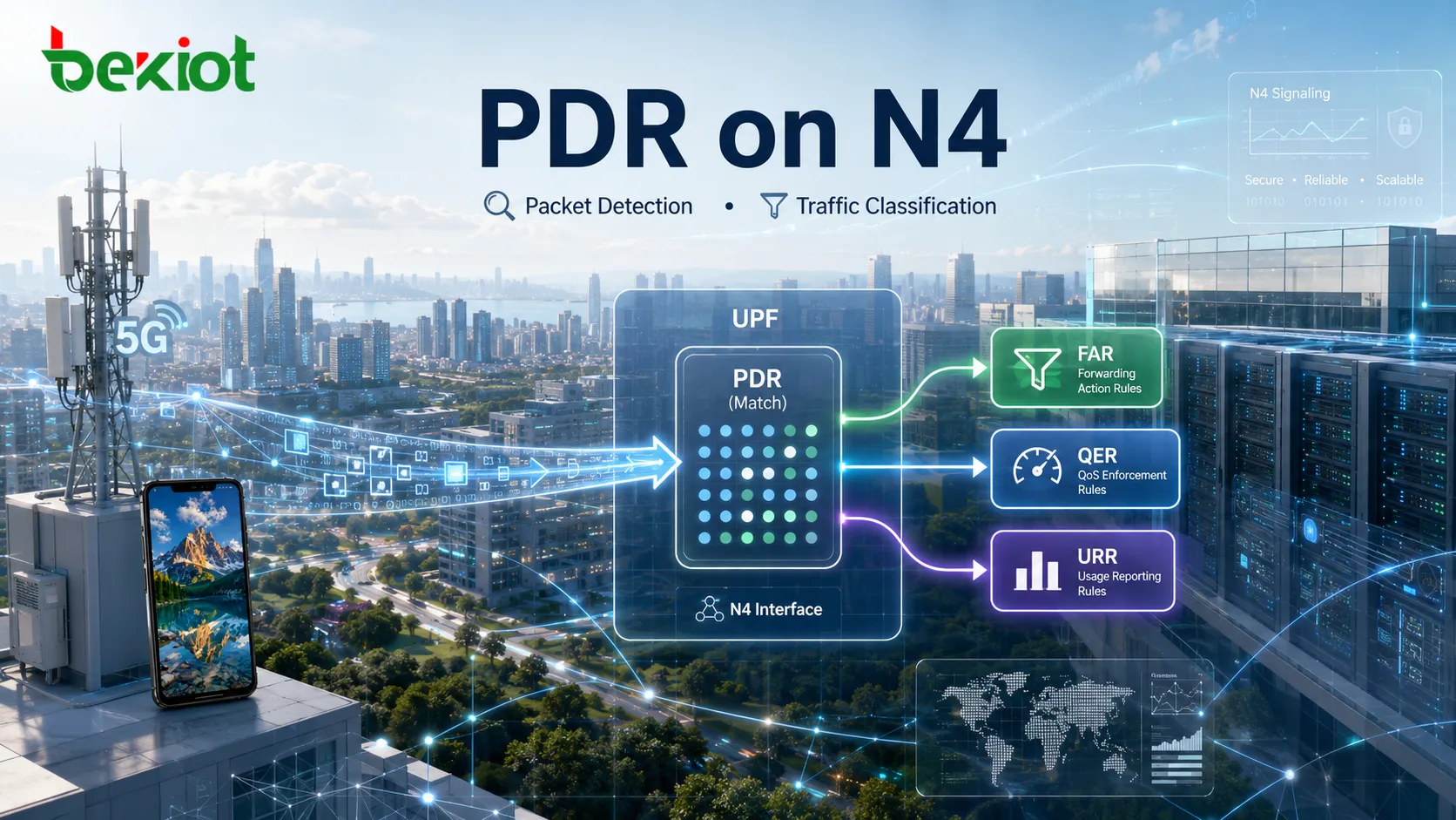
When a UPF receives a user-plane packet, it does not immediately decide where that packet should be forwarded. It first needs to determine which PFCP session the packet belongs to and which processing rule should apply. Within the PFCP rule framework on the N4 interface, the PDR (Packet Detection Rule) handles this first stage of packet processing. A PDR tells the UPF which packets belong to a particular traffic category. Once a packet matches, the UPF can apply the associated FAR, QER, URR, and other rules for forwarding, QoS enforcement, and usage reporting.
The easiest way to understand PDR is to separate three different responsibilities: PDR identifies the traffic, PDI defines the matching conditions, and FAR/QER/URR determine what happens after a match. Keeping these roles separate makes PFCP packet processing much easier to follow than trying to memorize every individual IE.
What Problem Does a PDR Solve on the N4 Interface?
N4 is the control interface between the SMF and UPF in the 5G Core. The SMF uses PFCP sessions to install user-plane processing rules in the UPF, and PDR is the rule type responsible for detecting and classifying packets. A PDR is commonly created during PFCP Session Establishment and can later be added, removed, or updated through PFCP Session Modification. In other words, packet classification is controlled by rules provisioned by the SMF according to the current PDU Session, traffic flow, and forwarding requirements.
A single PFCP session can contain multiple PDRs. The same PDU Session, for example, normally needs separate rules for uplink and downlink traffic. Additional PDRs may be required when the session contains multiple service data flows, different QoS Flows, or more granular traffic classifications. A PDR can therefore be viewed as the UPF's traffic-selection rule: it determines what kind of packet has arrived before other rules decide how that packet should be processed.
How Does the UPF Find the Matching PDR?
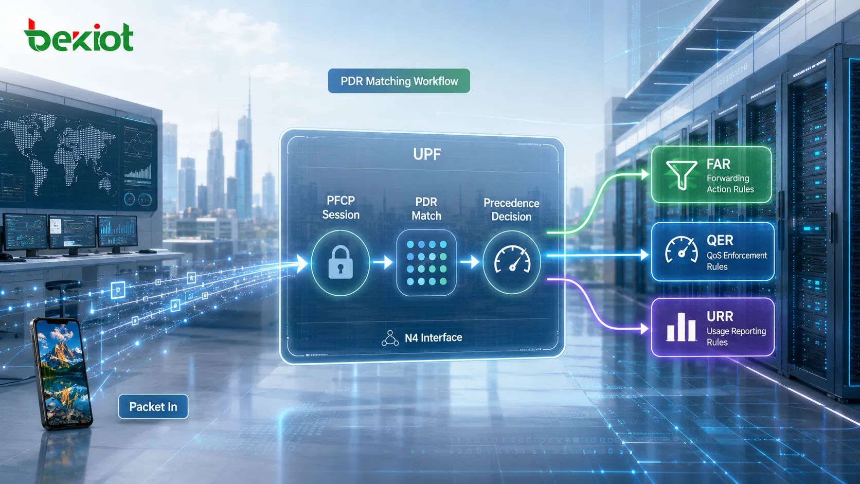
Packet processing in the UPF follows a defined sequence. After a packet enters the UPF, the function first identifies the corresponding PFCP session and then evaluates the PDRs associated with that session. If more than one PDR could potentially match, the UPF uses the Precedence value to determine their relative priority. A lower Precedence value represents higher precedence, so higher-priority rules are evaluated before lower-priority rules when searching for a match.
Once a PDR matches, the PDR itself does not perform every subsequent packet-processing operation. Instead, it can reference other PFCP rules:
FAR (Forwarding Action Rule): determines how the packet should be handled and forwarded, including whether it should be forwarded, dropped, buffered, or sent toward a particular destination interface.
QER (QoS Enforcement Rule): applies QoS-related controls such as gating, rate enforcement, and other traffic treatment.
URR (Usage Reporting Rule): measures traffic usage and provides reporting information that can be used for charging, monitoring, or policy-related purposes.
The overall UPF processing path can therefore be simplified as:
Identify the PFCP session → evaluate PDRs by Precedence → classify the packet → apply FAR/QER/URR. The order matters. FAR answers the question of how a packet should be handled, but the UPF first needs a PDR to establish which packet or traffic flow the action applies to.
What Are the Main Parameters in a PDR?
A Create PDR contains a number of Information Elements, but only a smaller set needs to be understood first when studying packet-detection behavior. These parameters define how the rule is identified, how packets are matched, and which subsequent processing rules are associated with the result.
| Parameter | Main Function |
|---|---|
| PDR ID | Uniquely identifies the PDR within the PFCP session and distinguishes it from other packet-detection rules |
| Precedence | Defines the relative priority of the PDR when multiple rules are evaluated; lower values indicate higher precedence |
| PDI | Contains the packet-detection criteria used by the UPF to determine whether incoming traffic matches the PDR |
| Outer Header Removal | Indicates whether the UPF should remove an outer protocol header, such as a GTP-U/UDP/IP header on uplink traffic |
| FAR ID | References the FAR that defines the forwarding action for matching packets |
| URR ID | References a URR used for traffic measurement and usage reporting |
| QER ID | References a QER that applies QoS-related treatment to the matching traffic |
| Activate Predefined Rules | Activates one or more predefined rules already available to the UPF |
| Activate Time / Deactivate Time | Defines when the PDR becomes active and when it stops being active |
Among these parameters, the element that actually defines which packets can match the PDR is the PDI (Packet Detection Information). FAR ID and QER ID reference actions that take place after traffic has been classified; PDI contains the information used to perform the classification itself.
How Does PDI Define Packet-Matching Conditions?
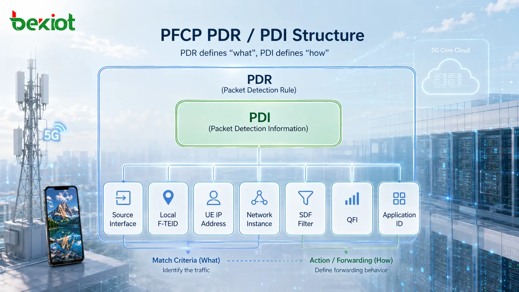
PDI can be understood as the set of packet-detection conditions inside a PDR. It is not a single field. Instead, it contains multiple parameters that can be combined to identify traffic according to where the packet entered the UPF, its tunnel information, UE address, service-flow characteristics, and QoS information. Common PDI parameters include:
Source Interface: identifies the logical side from which the packet arrives, such as Access for access-side traffic or Core for traffic arriving from the core or data-network side.
Local F-TEID: can be used to match the TEID and related addressing information associated with a GTP-U tunnel, making it particularly important when detecting uplink tunnel traffic.
Network Instance: identifies a logical network configured in the UPF, such as an Internet or IMS-related network instance.
UE IP Address: matches traffic according to the UE source or destination IP address, depending on the direction of the packet.
Traffic Endpoint ID: identifies a traffic endpoint that can be used in supported PDI optimization scenarios.
SDF Filter: provides more granular filtering based on parameters such as source and destination addresses, protocol, ports, and traffic direction.
Application ID: can be used for application-level traffic identification when the required application-detection capability is available in the UPF.
QFI (QoS Flow Identifier): identifies the QoS Flow associated with the packet.
Source Interface Type: provides additional information about the 3GPP interface associated with the source, such as N3, N6, or N9.
When multiple matching parameters are present in the PDI, they collectively define the packet-detection condition. The incoming packet must satisfy the applicable criteria before the PDR is considered a match. This allows the SMF to create rules ranging from broad session-level classification to much more specific service-flow detection.
How Granular Can Traffic Detection Become with an SDF Filter?
Source Interface, F-TEID, and UE IP Address may be sufficient to identify a session or a broad category of traffic, but they do not always distinguish individual service data flows. An SDF Filter provides more granular classification. Its Flow Description can include source IP address, destination IP address, protocol number, source port, destination port, and traffic direction. These fields allow the UPF to distinguish specific IP flows rather than treating every packet associated with a UE in the same way.
An SDF Filter can also carry additional matching information:
TOS / Traffic Class: matches the IPv4 Type of Service or IPv6 Traffic Class field.
Security Parameter Index (SPI): can be used when matching traffic associated with an IPsec Security Association.
Flow Label: matches the Flow Label contained in an IPv6 header.
SDF Filter ID: identifies the associated SDF Filter for management and reference purposes.
This creates a layered classification model. PDI parameters such as the interface, tunnel, and UE address can first narrow the traffic to a particular context, while the SDF Filter can identify individual IP flows within that context. Where application identification is also supported, the UPF can apply an additional application-level classification mechanism rather than relying only on addresses and ports.
What Is the Difference Between Uplink and Downlink PDRs?
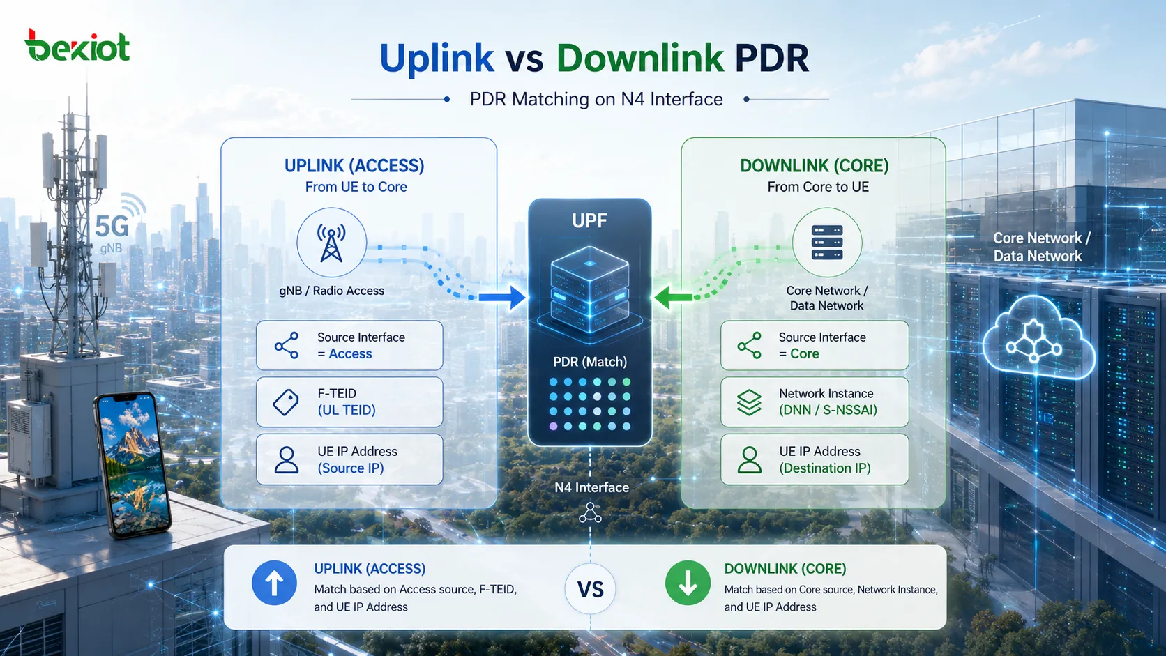
Comparing uplink and downlink traffic is one of the clearest ways to understand how PDRs operate. Both directions use the same general rule structure, but the packets enter the UPF from different interfaces and therefore require different detection criteria.
For typical uplink traffic, packets arrive at the UPF from the radio access side. The PDI can therefore use Source Interface = Access. The rule can additionally use a Local F-TEID to identify the GTP-U tunnel and a UE IP Address to identify the UE traffic. A typical uplink PDR may therefore require:
Source Interface is Access;
the incoming GTP-U packet matches the specified F-TEID, including the relevant TEID and address information;
the UE IP address matches the address associated with the session.
When the conditions are satisfied, the PDR matches. Because traffic received over N3 is normally encapsulated in GTP-U, Outer Header Removal can instruct the UPF to remove the GTP-U/UDP/IP outer headers before the packet is processed according to the associated FAR.
Downlink detection starts from the opposite direction. Packets typically arrive from a data network toward the UPF, so the PDI can use Source Interface = Core. In this case, parameters such as the Network Instance and UE IP Address can be used to determine which PDU Session the packet belongs to. A typical downlink PDR may therefore require:
Source Interface is Core;
the Network Instance matches the required logical network, such as "internet" or "ims";
the packet destination matches the UE IP address associated with the session.
After the downlink PDR matches, the associated FAR determines how the packet should be forwarded toward the access side, including the required tunnel forwarding behavior. The difference between uplink and downlink PDRs therefore reflects the direction from which packets enter the UPF and the information available for identifying them.
How Do PDR, FAR, QER, and URR Work Together?
A PDR solves the packet-identification problem, but it does not represent the entire user-plane processing policy. PFCP separates packet detection, forwarding, QoS enforcement, and usage measurement into different rule types. This separation allows each rule to perform a specific function while still operating within the same PFCP session.
PDR: What traffic is this? (Detection and classification)
FAR: What should happen to it and where should it go? (Forwarding action)
QER: What QoS treatment should apply? (QoS enforcement)
URR: How should its usage be measured and reported? (Usage reporting)
Consider an uplink packet that matches a PDR. Once the UPF determines which UE and service flow the packet belongs to, it can remove the required GTP-U outer header, apply the forwarding behavior referenced by the FAR, enforce the applicable QER, and account for traffic according to the associated URR. The packet-detection result therefore provides the context needed for all subsequent operations.
From an engineering perspective, PDR should not be viewed as an isolated forwarding policy. It is the entry point into the PFCP user-plane rule set. Once the relationship between PDR for classification, PDI for matching criteria, and FAR/QER/URR for subsequent processing is clear, parameters such as Source Interface, F-TEID, UE IP Address, and SDF Filter become much easier to understand in actual N4 signaling and packet analysis.
FAQ
Precedence is used when the UPF evaluates PDRs within a PFCP session. If the PDI conditions of two rules are completely mutually exclusive, however, the two PDRs cannot match the same packet, so their relative precedence does not change the final match. Precedence becomes particularly important when rule conditions overlap and more than one PDR could otherwise match the same traffic.
If the UE address used as a PDI matching condition changes, the rule associated with that address must also reflect the updated session information. The SMF can update relevant PDR information through PFCP Session Modification so that the UPF continues to classify the UE traffic correctly.
Yes. SDF filtering does not require every possible field to restrict traffic to one specific port. Depending on the rule definition, port ranges or less restrictive matching conditions can be used to cover a broader set of traffic. Address masks can also be used where the applicable filter definition requires matching an address range.
If an incoming packet cannot be associated with an applicable PDR, the UPF has no matching packet-processing rule for that traffic within the relevant context. The resulting handling depends on the applicable PFCP rules, UPF implementation, and session configuration. In troubleshooting, an unexpected PDR mismatch is therefore an important point to investigate when traffic reaches the UPF but is not forwarded as expected.
PFCP supports predefined rules that are already provisioned in the UP function and can be activated when required. Instead of repeatedly provisioning every rule parameter for applicable scenarios, the control plane can activate the corresponding predefined rule. This can reduce the amount of signaling required when the same rule sets are reused across suitable sessions.