A common troubleshooting scenario in 5G networks looks straightforward at first: the UE registers successfully, the PDU Session is established, and an IP address is assigned correctly, yet web access fails and even basic Ping traffic does not work. Packet captures may show traffic arriving at the UPF over N3, but no corresponding packet leaves on the expected path. If troubleshooting remains focused only on AMF signaling and the PDU Session establishment result, the actual cause can be difficult to isolate.
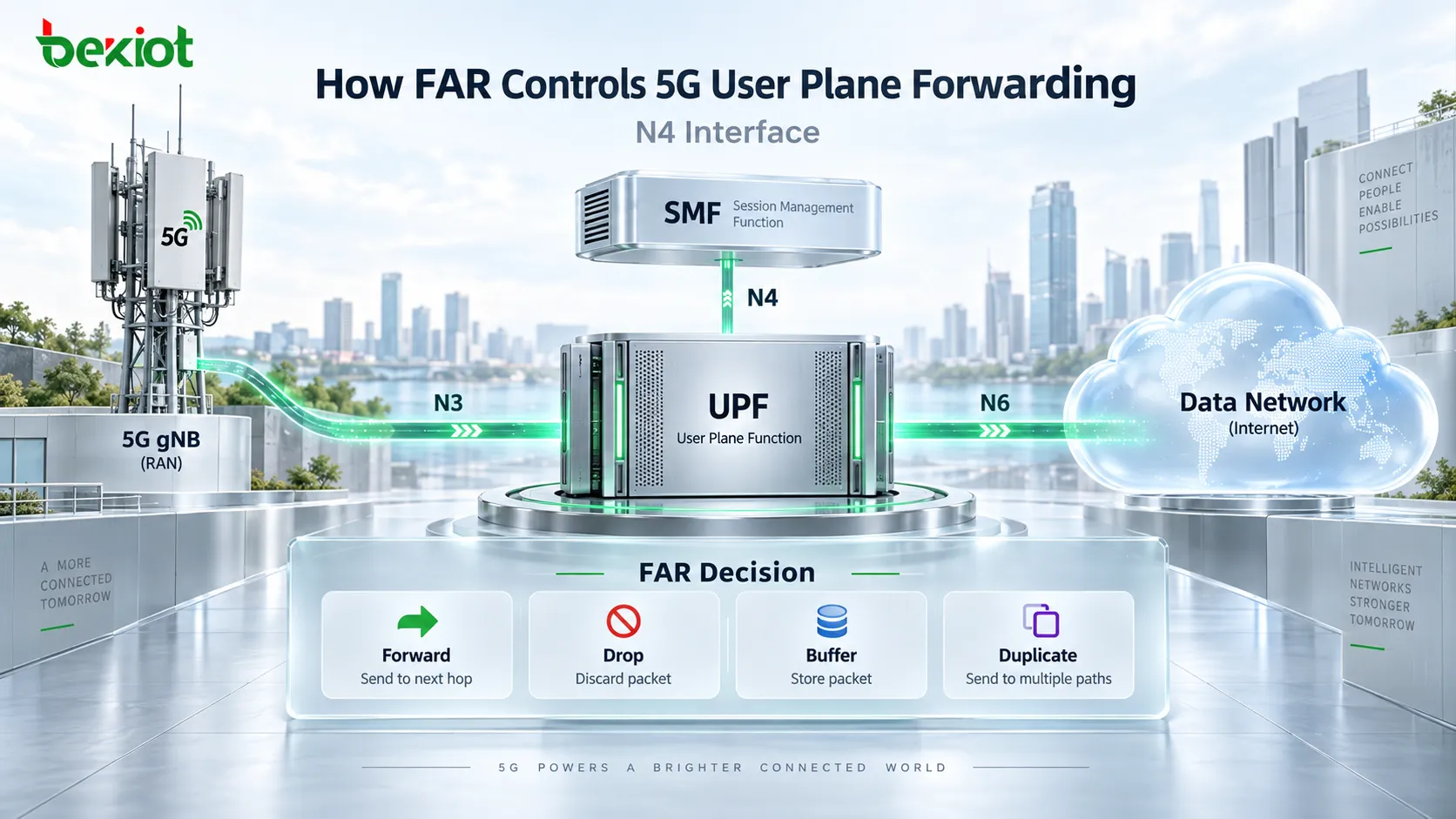
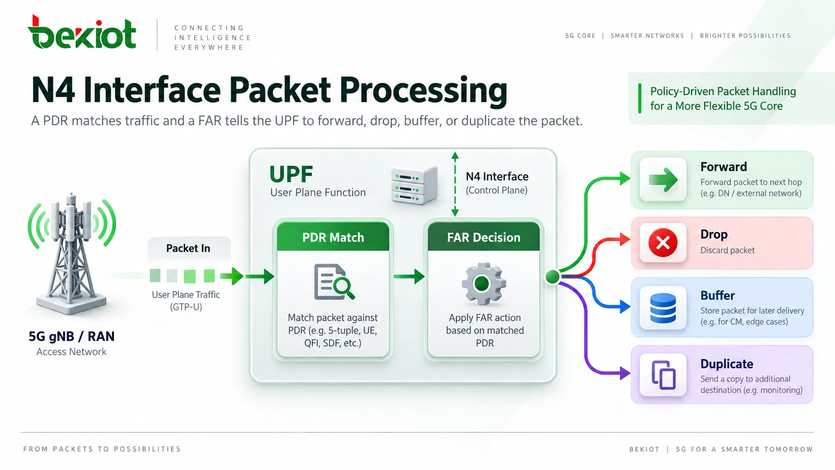
A successfully established PDU Session does not automatically mean that the user plane forwarding path is operational. After receiving a packet, the UPF first uses a PDR to identify the traffic and then applies the associated FAR (Forwarding Action Rule) to determine what happens next: forward, drop, buffer, or duplicate the packet. The FAR can also define the destination interface and whether an outer GTP-U tunnel header needs to be created.
From a troubleshooting perspective, the distinction is useful: a PDR answers "Which session and traffic flow does this packet belong to?", while a FAR answers "Now that the packet has been identified, what should the UPF do with it?" When control-plane procedures appear normal but user traffic still fails, the FAR on the N4 interface becomes an important point to investigate.
Why Does a Successful PDU Session Not Guarantee User Plane Connectivity?
Completion of the PDU Session Establishment procedure only confirms that the required control-plane session resources have been initialized. Actual application traffic still depends on the complete user plane path involving the gNB, N3, UPF, and N6.
For a typical Internet PDU Session, uplink traffic travels from the UE to the gNB, is encapsulated in a GTP-U tunnel, and then reaches the UPF over N3. The UPF needs to remove the applicable outer tunnel header, identify the traffic, and forward the original packet toward the data network. The downlink direction works in reverse: traffic enters the UPF from N6, the UPF identifies the corresponding PDU Session, obtains the gNB user plane tunnel information, adds the required GTP-U outer header, and sends the packet toward the gNB over N3.
This forwarding behavior does not become available simply because the PDU Session has been created. The SMF must provision the appropriate PFCP rules to the UPF over N4. The PDR identifies matching traffic, while the FAR defines the forwarding action to apply after the traffic has been classified. Both rule types are required for correct user plane processing.
When all control-plane signaling appears normal but the service remains unavailable, the problem can be broken down into two core questions:
Does the PDR correctly identify the current traffic?
After the packet is identified, does the associated FAR contain the correct processing and forwarding parameters?
Focusing on the relationship between the PDR and FAR is often more efficient than repeatedly reviewing the entire PDU Session establishment procedure from the beginning.
What Does a FAR Actually Tell the UPF to Do?
A FAR is a forwarding rule within the PFCP framework. It is provisioned by the SMF to the UPF over N4 and associated with traffic through the FAR ID referenced by a PDR. Once a packet matches that PDR, the UPF executes the processing behavior defined by the referenced FAR.
A FAR can contain several Information Elements. For user plane troubleshooting, the following fields are particularly important:
| FAR Parameter | Main Function |
|---|---|
| FAR ID | Uniquely identifies the FAR instance so that a PDR can reference the correct forwarding rule |
| Apply Action | Defines the basic packet action, including forwarding, dropping, buffering, or duplication |
| Forwarding Parameters | Defines the destination, network instance, tunnel encapsulation, and other parameters used when forwarding is required |
| Duplicating Parameters | Defines how a duplicated copy of the packet should be forwarded when traffic duplication is enabled |
| BAR ID | References a Buffering Action Rule used to control packet buffering behavior |
In practice, Apply Action and Forwarding Parameters are the two elements most easily confused. Apply Action answers "What action should be taken?", while Forwarding Parameters answer "If the packet is forwarded, how and where should it be sent?"
Seeing the FORW flag in Apply Action does not by itself prove that the downlink path is complete. The destination interface, Network Instance, outer-header creation information, and other related forwarding parameters still need to be correct.
How Does Apply Action Determine the First Packet-Processing Step?
Apply Action is represented by a set of bit flags that instruct the UPF which basic operations should be applied to matched packets. These flags are not simply mutually exclusive choices; their meaning needs to be interpreted in the context of the PFCP session and the service scenario.
DROP: Discard the matching packet.
FORW: Forward the packet according to the applicable forwarding parameters.
BUFF: Buffer the packet instead of forwarding it immediately.
NOCP: Used with buffering scenarios to notify the control plane when downlink data requiring buffering arrives.
DUPL: Create a duplicate copy of the packet and process that copy according to the Duplicating Parameters.
Why Are BUFF and NOCP Needed?
A typical use case occurs when the UE is idle and an immediate downlink user plane path is not available. Downlink traffic may already have reached the UPF, but it cannot yet be delivered to the UE. The UPF can buffer the packet and, where required, use the associated control-plane notification behavior so that further procedures such as paging or user plane path recovery can be initiated.
BUFF only indicates that buffering is required. Details such as how buffering is handled are associated with the BAR, so troubleshooting should not rely on the BUFF flag alone.
Why Is DUPL More Than Simply "Forwarding the Packet Again"?
DUPL creates a separate copy of the packet. The original packet continues to follow its normal processing path, while the duplicated copy is controlled independently by the Duplicating Parameters. The duplicate may use a different destination interface, outer-header configuration, transport-level marking, or forwarding policy.
For this reason, mirrored or duplicated traffic should not automatically be assumed to follow the same path as the original service traffic. The duplication parameters need to be checked separately.
How Do Forwarding Parameters Determine Where a Packet Actually Goes?
When Apply Action includes FORW, the Forwarding Parameters determine the actual forwarding path. Several fields are particularly important when troubleshooting user plane failures.
Destination Interface
Destination Interface defines the logical interface toward which the UPF should send the packet after processing. In a typical downlink scenario, it is set to Access, meaning that the packet should be forwarded toward the gNB. Uplink traffic is generally forwarded toward the Core side.
An incorrect Destination Interface can create a difficult-to-detect failure: the PDR matches correctly, but the packet is sent toward the wrong logical interface, while the control plane may show no obvious error.
Network Instance
Network Instance identifies the logical network context used for forwarding. It is particularly important in deployments with multiple DNNs, slices, or data networks where traffic needs to remain separated.
When troubleshooting N6 connectivity or private-network services, checking physical reachability is not enough. The Network Instance in the FAR should also match the corresponding UPF configuration. A mismatch can prevent traffic from being routed into the expected network context.
Outer Header Creation
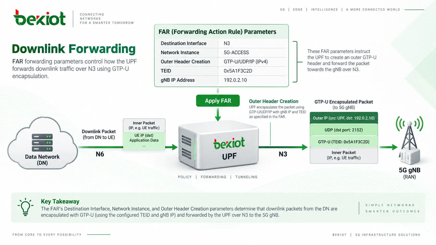
Outer Header Creation is one of the key parameters for downlink forwarding over N3. A packet entering the UPF from N6 contains the original UE payload. Before that packet can be sent to the gNB over N3, the UPF needs to add the required GTP-U/UDP/IP outer encapsulation.
Outer Header Creation provides the information needed for this operation, including the gNB user plane address, the N3 tunnel TEID, and the outer-header type.
Many cases where downlink traffic reaches the UPF but no corresponding packet appears on N3 can be traced to missing or incorrect information in this part of the FAR, such as an incorrect TEID or gNB address.
Other Forwarding Parameters
Forwarding Parameters can also include Redirect Information, Transport Level Marking, Forwarding Policy, Header Enrichment, Linked Traffic Endpoint ID, Proxying, Destination Interface Type, and other optional information.
Transport Level Marking can be used to apply the required DSCP marking to forwarded packets. Forwarding Policy can reference a forwarding policy configured locally on the UPF. Header Enrichment supports additional header processing in applicable services. Not every FAR carries all of these Information Elements; the actual contents depend on the PFCP signaling and service requirements.
Why Might a Downlink FAR Be Updated After the Session Is Established?
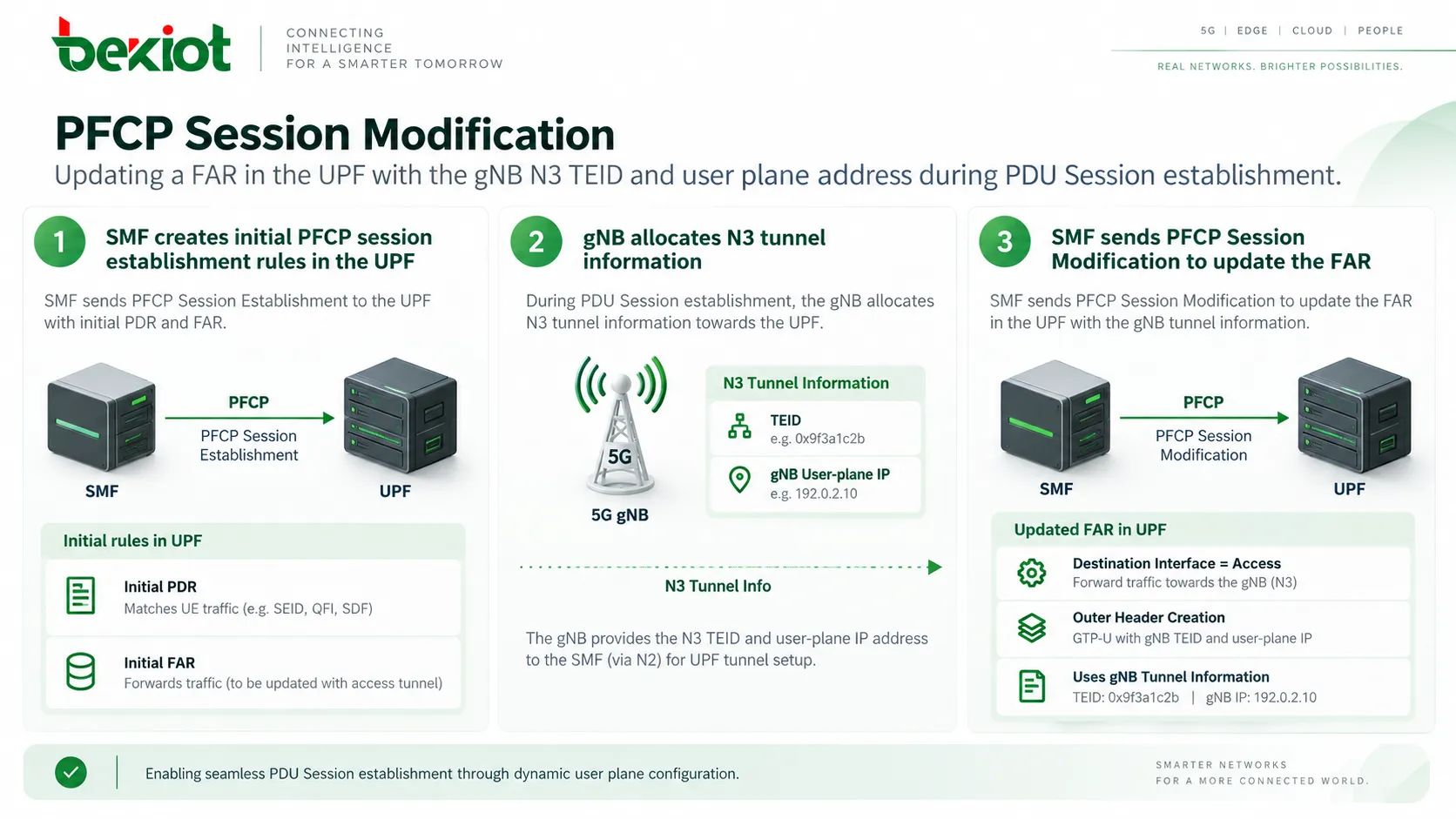
During the initial PDU Session Establishment procedure, the SMF can create the first PDRs and FARs in the UPF. At that point, however, the gNB may not yet have completed allocation of the downlink N3 user plane resources. The final tunnel TEID and gNB user plane address may therefore not yet be available to the SMF.
Once the gNB has allocated those resources and the corresponding N3 user plane information becomes available to the SMF, the SMF can send a PFCP Session Modification to update the existing FAR in the UPF with the required downlink tunnel parameters.
The updated downlink FAR can then include the key forwarding information:
Destination Interface = Access, indicating forwarding toward the access side;
the applicable Network Instance;
Outer Header Creation = GTP-U/UDP/IPv4 or another applicable outer-header type;
the gNB N3 user plane IP address and the allocated tunnel TEID.
This is why troubleshooting should not stop after examining only the PFCP Session Establishment Request. The initial FAR may contain only the basic forwarding action, while the information required to build the actual N3 downlink tunnel can be added later through PFCP Session Modification.
If that later update is ignored during analysis, a normal staged rule-provisioning process can easily be mistaken for a missing or incomplete FAR configuration.
How Does a FAR Send Downlink Traffic Back into the N3 Tunnel?
Following the complete downlink packet path makes the role of the FAR easier to understand.
A packet from an external server reaches the UPF through N6. The UPF uses a PDR to identify the traffic and associate it with the correct PDU Session. It then reads the FAR referenced by that PDR.
If Apply Action includes FORW, the UPF evaluates the Forwarding Parameters. Destination Interface set to Access means the packet should be sent toward the radio access side. Outer Header Creation contains the gNB tunnel address and TEID needed to construct the GTP-U outer header. The UPF then encapsulates the original packet and sends it to the gNB over N3.
The complete path can be summarized as:
Downlink packet arrives on N6 → PDR identifies UE traffic → FAR applies FORW → UPF obtains the gNB N3 tunnel parameters → UPF creates the GTP-U outer header → packet is transmitted to the gNB over N3.
This also clarifies the difference between FAR and GTP-U. GTP-U is the tunneling protocol that carries the user data, while the FAR is the UPF decision rule that controls whether an outer tunnel header should be created, which tunnel information should be used, and which logical interface should receive the packet.
An incorrect TEID observed in an N3 packet capture is therefore only the visible symptom. The investigation should continue back toward the control plane: Was the correct user plane information allocated by the gNB? Did the SMF receive it correctly? Was it then written into the appropriate FAR through the N4 update?
How Can FAR Be Used to Troubleshoot a PDU Session That Is Up but Has No Data Connectivity?
If UE registration is normal and the PDU Session has been established but the service still does not work, troubleshooting can follow the actual UPF packet-processing sequence rather than replaying the entire registration procedure from the beginning.
A practical FAR troubleshooting sequence is:
Confirm that the packet reaches the UPF. If no packet arrives on N3 or N6, the problem is upstream of the FAR and should first be investigated on the UE, gNB, or transport path.
Confirm that the PDR matches the packet. A FAR has no traffic to act on unless the packet is first identified by the associated PDR.
Verify the FAR ID referenced by the PDR. Make sure that a correctly matched packet is not associated with the wrong forwarding rule.
Inspect Apply Action. Determine whether the configured behavior is FORW, DROP, BUFF, or a combination of applicable flags.
Check Destination Interface and Network Instance. Confirm that the packet is being sent toward the correct logical direction and network context.
Check Outer Header Creation. For downlink N3 traffic, verify the gNB address, TEID, and outer-header type.
Review PFCP Session Modification messages. Do not examine only the initial Create FAR. Confirm that the gNB tunnel information was subsequently updated in the UPF.
Cross-check the N3 and N6 packet captures. Compare the behavior expected from the PFCP rules with the packets actually transmitted by the UPF.
The main advantage of this approach is that control-plane rules and user-plane packet captures can validate each other. PFCP signaling shows how the UPF should forward the packet, while N3 and N6 captures show what the UPF actually did.
When those two views do not match, the fault domain can usually be narrowed to one of three areas: incorrect N4 rule provisioning, incorrect UPF rule execution, or a problem in the user plane transport path. This is much more efficient than searching across the entire 5G Core without a clear direction.
FAQ
What Is the Main Difference Between a FAR and a PDR?
A PDR performs packet detection and classification, answering questions such as which session and traffic flow a packet belongs to. A FAR defines what happens after that match, including how the packet should be handled and where it should be forwarded. A PDR references the corresponding FAR through the FAR ID.
Why Can Forwarding Still Fail When Apply Action Includes FORW?
FORW only indicates that forwarding should be performed. Successful forwarding still depends on the associated Forwarding Parameters. If the Destination Interface, Network Instance, or Outer Header Creation information is incorrect, the packet may still fail to reach the expected destination. An incorrect N3 TEID or gNB user plane address is a typical example.
Why Does the First PFCP Session Establishment FAR Sometimes Lack Complete N3 Tunnel Information?
PDU Session establishment is a multi-step procedure. When the initial PFCP session is created, the gNB may not yet have allocated the final downlink N3 user plane resources. Once the gNB tunnel address and TEID become available, the SMF can update the FAR through PFCP Session Modification. Troubleshooting therefore needs to follow the subsequent N4 exchanges as well as the initial establishment message.
How Are Outer Header Creation and PDR Outer Header Removal Related?
They apply to opposite directions of tunnel processing. For uplink traffic arriving from N3, Outer Header Removal is used to remove the applicable GTP-U outer header. For downlink traffic leaving the UPF toward N3, the FAR's Outer Header Creation provides the information needed to build the new GTP-U outer header. Together, they support the two directions of user plane tunnel encapsulation and decapsulation.
If the TEID on N3 Is Wrong, Should Troubleshooting Focus Only on GTP-U?
No. An N3 packet capture only shows that the TEID being used is incorrect. The tunnel information originates from the gNB, is processed by the SMF, and is then provisioned into the FAR over N4. Troubleshooting should therefore trace the gNB allocation, the information received by the SMF, and the FAR update in the PFCP Session Modification procedure to locate the actual cause.