Loop current is the electrical current that flows through a closed circuit loop after a device, line, sensor, or terminal completes the path. In communication and control systems, it is often used to indicate line status, power field devices, transmit analog values, supervise circuits, or confirm that an electrical path is active.
The term appears in several practical areas. In analog telephony, loop current flows through the subscriber line when a telephone goes off-hook, helping the exchange, PBX, or gateway detect that the line is in use. In industrial instrumentation, a current loop such as 4–20 mA carries measurement values from sensors to controllers. In alarm and safety systems, loop current may help supervise whether a circuit is normal, open, shorted, or triggered.
A Closed Path That Carries Meaning
Electrical current only flows when there is a complete path. This simple principle becomes useful in real systems because the presence, absence, or value of current can represent information. A device can detect whether a line is idle, active, faulty, or carrying a measured signal by observing current behavior.
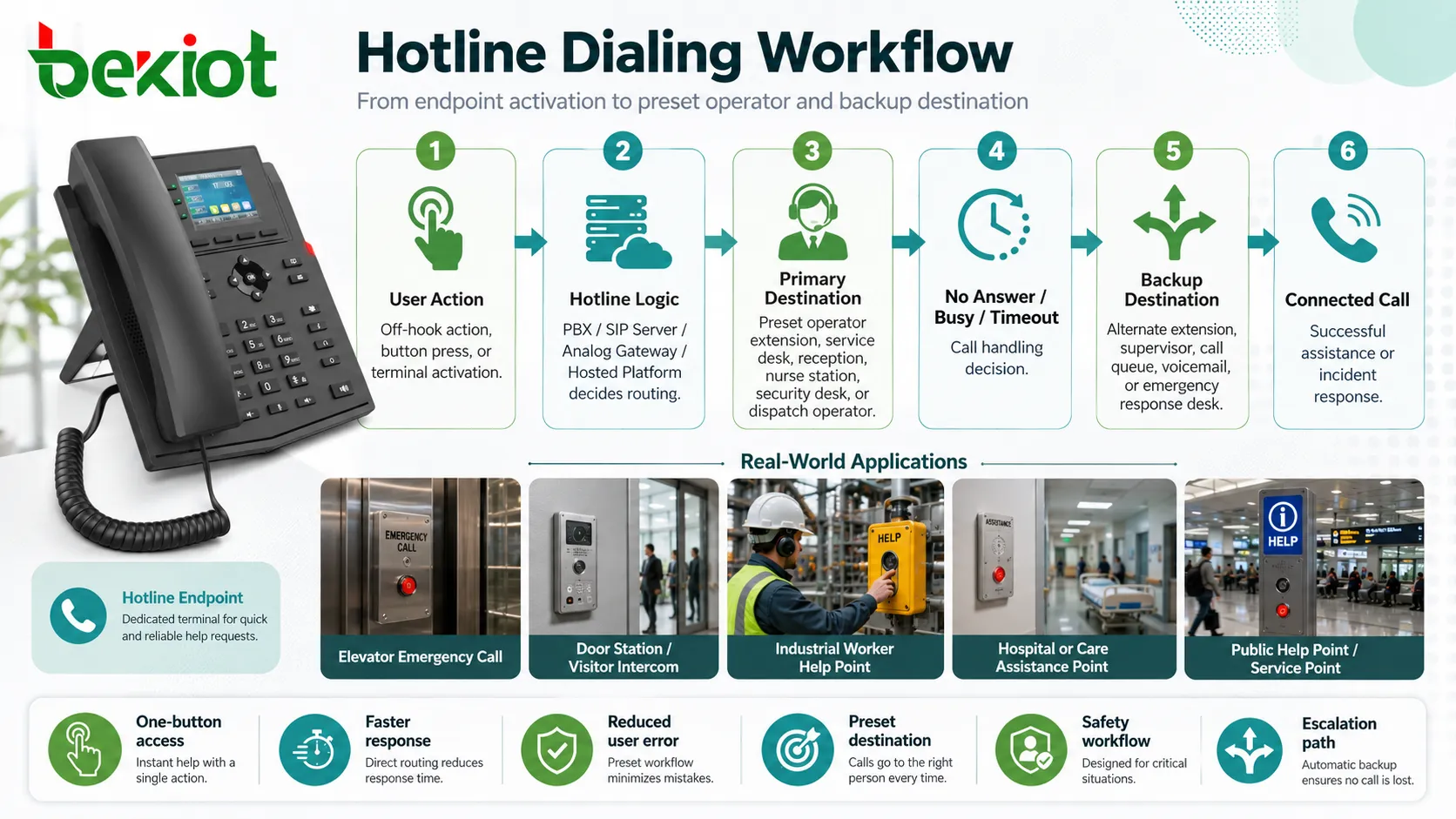
In analog telephone systems, the line is usually in an idle state when the handset is on-hook. When the user lifts the handset, the circuit closes and current flows through the line. This change tells the central office, PBX, or analog gateway that the user wants service. The system can then provide dial tone, accept digits, route the call, and supervise call state.
In industrial and building systems, the same basic idea is used differently. A sensor may regulate the current in a loop to represent temperature, pressure, level, flow, position, or gas concentration. A control panel may monitor loop current to confirm whether field wiring is intact. The current becomes both an electrical quantity and a system status signal.

How the Circuit Becomes Active
Power Source
A loop needs a source of electrical energy. In telephony, this may come from a central office line card, PBX port, analog telephone adapter, or gateway interface. In industrial instrumentation, power may come from a loop power supply, controller input card, signal conditioner, or transmitter supply.
The available voltage must be high enough to drive the required current through the complete loop, including cable resistance, device burden, protection components, and input circuitry. If the supply is too weak, the loop may become unstable or fail under longer cable runs.
Load and Field Device
The connected device controls or consumes part of the loop energy. A telephone set, analog endpoint, sensor transmitter, relay input, alarm contact, or measurement device may act as part of the loop. Its impedance or internal electronics affects how current flows.
For example, an analog telephone changes line condition when it goes off-hook. A 4–20 mA transmitter changes current value according to the measured process variable. An alarm loop changes state when a contact opens or closes.
Return Path
The return path completes the circuit. If the conductor is broken, disconnected, corroded, or improperly terminated, current cannot flow normally. This may appear as no dial tone, failed sensor reading, open loop alarm, or offline field device.
Because loop systems depend on continuity, wiring quality is critical. Loose terminals, oxidized connectors, damaged insulation, water ingress, and poor splicing can create intermittent problems that are difficult to diagnose.
Monitoring Input
The receiving side detects the current, voltage drop, or state change. A PBX detects off-hook current. A PLC analog input converts current into a measurement value. An alarm panel evaluates whether the circuit is normal or abnormal.
The monitoring input must match the loop type. Connecting a current-loop sensor to the wrong input range, using the wrong polarity, or exceeding input burden can cause incorrect readings or equipment damage.
Common Forms in Real Systems
Telephone Subscriber Loops
In traditional analog telephony, loop current is central to line supervision. When a phone is on-hook, the circuit is not drawing normal talking current. When the user lifts the handset, the loop closes and current flows. The exchange or PBX detects the condition and begins call processing.
This same principle is still relevant when analog phones connect to VoIP gateways, ATAs, elevator phones, emergency phones, hotel room phones, fax devices, or legacy PBX ports. Even if the core network is IP-based, the analog port still depends on loop behavior.
4–20 mA Instrumentation
The 4–20 mA current loop is widely used in industrial measurement. A transmitter sends a current proportional to the measured value. Typically, 4 mA represents the lower end of the measurement range and 20 mA represents the upper end.
This method is valued because current signals are less sensitive to voltage drop over long cables than voltage signals. It also allows fault detection because a reading near 0 mA can indicate an open circuit, failed transmitter, or wiring problem rather than a valid low measurement.
Alarm Supervision Circuits
Alarm panels and safety systems may use supervised loops to detect open circuits, short circuits, normal status, or alarm conditions. End-of-line resistors, current thresholds, and input supervision help the panel distinguish between a real trigger and a wiring fault.
This is important for security, fire alarm, emergency call, access control, and facility monitoring systems where wiring integrity must be known before an emergency occurs.
Control and Relay Loops
Control circuits use loop current to energize relays, activate inputs, drive indicators, or confirm command paths. In simple systems, a switch closes the loop and a load turns on. In more complex systems, loop status may be read by controllers and software.
These loops are common in industrial machines, building automation, pump control, lighting panels, and field signaling circuits.
Why It Is Useful in Deployment
One practical benefit is simplicity. A loop can carry both power and signal in a straightforward way. This reduces the number of conductors and makes field wiring easier to understand. For many analog and industrial systems, the current itself becomes the message.
Another benefit is supervision. The system can detect whether a circuit is active, idle, disconnected, shorted, or outside expected range. This helps technicians identify line faults and helps operators know whether field devices are healthy.
Current-based signaling can also work well over distance when designed correctly. In instrumentation, current loops can tolerate cable voltage drop better than many voltage-based signals. In telephony, loop supervision allowed telephone exchanges to manage millions of subscriber lines using simple electrical states.
The value of loop current is that it turns electrical continuity into operational information: active, idle, measured, failed, triggered, or supervised.
Design Factors Before Installation
Voltage Budget
The loop power source must provide enough voltage for the full circuit. Designers should consider cable length, conductor resistance, device voltage drop, input burden, protection devices, and temperature effects.
If the voltage budget is too small, the circuit may work during bench testing but fail after installation because the real cable run is longer or the connected load is higher.
Current Range
The expected current range must match the receiving equipment. A telephone port, analog input, relay input, alarm panel, or sensor receiver may each expect a different current behavior.
Using the wrong input range can cause false status, inaccurate readings, or damaged electronics. Project documentation should clearly state the expected normal, alarm, fault, and maximum current values.
Polarity
Some current loops are polarity-sensitive, especially when active electronics, diodes, surge protectors, or powered transmitters are used. Reversed polarity may stop the device from working or create unstable readings.
Polarity should be checked during commissioning. Color-coded wiring helps, but field verification is still important because cable pairs may be extended or spliced in multiple locations.

Cable Resistance
Long cable runs add resistance. In a current loop, this resistance creates voltage drop. If the power source cannot overcome that drop, the loop may fail to reach the required current.
Larger conductor size, shorter cable paths, suitable power supply voltage, and correct input burden selection can improve reliability over distance.
Isolation and Grounding
Grounding and isolation affect noise performance and safety. In industrial sites, ground potential differences can create unwanted current paths. In communication systems, poor grounding can introduce hum, noise, or surge risk.
Isolation modules, surge protectors, proper bonding, and careful shield termination may be needed in harsh or long-distance installations.
Maintenance Tips for Stable Operation
Measure Under Real Load
Loop current should be measured while the device is connected and operating under real conditions. A circuit may look normal when disconnected but fail when the actual field device draws current.
For telephone lines, technicians may check on-hook voltage, off-hook current, ringing behavior, and line resistance. For instrumentation loops, they may check current at zero, mid-range, and full-scale values.
Check Terminals and Splices
Loose or corroded terminals are common causes of intermittent current problems. Vibration, humidity, dust, temperature change, and poor workmanship can gradually weaken connections.
Maintenance should include physical inspection, not only software diagnostics. Tight terminals, clean contact surfaces, and protected junction boxes improve long-term reliability.
Look for Moisture and Leakage Paths
Water ingress can create leakage current, corrosion, false readings, or unstable loop behavior. Outdoor devices, underground cables, elevator pits, plant floors, and coastal environments are especially vulnerable.
Sealed enclosures, cable glands, drip loops, drainage, corrosion-resistant terminals, and regular inspection help reduce moisture-related faults.
Verify Calibration
In measurement systems, loop current must correspond to the correct physical value. A 12 mA signal should represent the expected mid-scale value only if the transmitter and controller scaling match.
After replacing sensors, controllers, or analog input cards, scaling and calibration should be checked. Wrong scaling can make a healthy signal appear incorrect.
Review Fault Thresholds
Some systems define current thresholds for open circuit, short circuit, normal state, alarm state, or sensor fault. If these thresholds are poorly configured, the system may miss faults or generate nuisance alarms.
Thresholds should match the device datasheet, cable conditions, end-of-line resistor design, and control panel input behavior.
Applications Across Systems
Analog Telephony
Telephone systems use loop current to detect off-hook and on-hook states. This allows PBX ports, central office lines, analog gateways, and ATAs to know when a user starts or ends a call.
Loop current is also relevant when troubleshooting analog phones, fax machines, elevator phones, emergency phones, hotel phones, and legacy line interfaces. Too little current may cause weak operation, while abnormal current may indicate wiring or device faults.
Industrial Process Control
In factories, utilities, chemical plants, water treatment facilities, and energy sites, current loops are used for measuring pressure, temperature, flow, level, valve position, and gas concentration.
The technology remains common because it is simple, robust, and compatible with many PLCs, DCS systems, recorders, and field transmitters.
Building Automation
Building systems may use current loops for HVAC sensors, pressure transducers, damper feedback, tank level sensors, pump status, and energy monitoring devices.
Reliable loop design helps building operators receive stable measurements and reduces false maintenance calls caused by wiring noise or incorrect scaling.
Safety and Alarm Systems
Supervised circuits in fire alarms, security systems, gas detection, access control, and emergency monitoring use loop behavior to identify normal, alarm, open, or short conditions.
These systems need careful installation because a wiring fault can look like a real alarm or hide a real alarm if supervision is poorly designed.
Remote Field Devices
Remote pumps, tanks, gates, cabinets, substations, and monitoring stations may use loop-based signals because the wiring is simple and can work over long distances when properly designed.
For outdoor installations, surge protection, grounding, water sealing, and cable shielding become especially important.

Common Fault Symptoms
No Current
No current usually indicates an open circuit, disconnected device, broken conductor, failed power supply, blown fuse, reversed wiring, or incorrect terminal connection. In telephony, it may appear as no off-hook detection or no dial tone. In instrumentation, it may appear as a zero or fault reading.
The first step is to check the power source, continuity, polarity, and physical wiring path.
Current Too Low
Low current may be caused by excessive cable resistance, weak supply voltage, high input burden, failing field device, poor terminal contact, or partial conductor damage.
This problem may appear only on long cable runs or when the field device reaches a certain operating condition.
Current Too High
High current can indicate a short circuit, wrong wiring, incorrect device type, failed transmitter, bypassed resistor, or damaged input circuit. It should be investigated quickly because excessive current may damage equipment.
Current-limited supplies and protective fuses help reduce the risk of serious damage.
Unstable Readings
Fluctuating current may come from loose terminals, electrical noise, poor shielding, moisture, failing sensors, unstable power, or ground loops. It may also occur when a measured process is truly changing rapidly.
Technicians should separate real process variation from electrical instability by checking the signal at multiple points in the loop.
False Status Indication
Alarm or telephony systems may show incorrect state when thresholds, resistors, line polarity, or device characteristics do not match the input design. For supervised circuits, wrong end-of-line resistor placement is a common issue.
Reviewing the wiring diagram and measuring actual current values can usually identify the mismatch.
Loop current problems are often physical before they are logical. Cable condition, terminals, polarity, moisture, and power capacity should be checked before assuming a software fault.
Deployment Checklist
Start by defining the loop purpose. A telephone loop, sensor loop, alarm supervision loop, and relay control loop do not have the same current range or diagnostic behavior.
Confirm the power source, expected current range, maximum loop resistance, cable length, conductor size, input burden, polarity, and protection components before installation.
Label field terminals clearly. Include loop number, signal type, polarity, device name, and destination. Good labeling reduces wiring mistakes and speeds up maintenance.
Measure and record baseline values during commissioning. Normal loop current, fault current, alarm current, and operating range values should be documented where applicable.
Protect outdoor and long-distance circuits with suitable surge protection, grounding, shielding, and enclosure sealing. Field conditions often determine long-term reliability more than the loop concept itself.
Long-Term Operation and Documentation
Loop-based systems are often expected to run for many years. To keep them reliable, maintenance teams should keep wiring drawings, calibration records, current measurements, device datasheets, terminal schedules, and fault history updated.
When a field device is replaced, the new device should be checked against the original loop design. A transmitter may have different voltage requirements. A telephone gateway may provide different line current. An alarm panel may use different supervision thresholds.
After modifications, technicians should retest the loop under normal and fault conditions. A circuit that appears connected may still fail to report the correct state if thresholds, scaling, or wiring order changed.
FAQ
Can loop current be measured with a normal multimeter?
Yes, if the meter supports the required current range and is connected correctly in series with the loop. Incorrect meter placement can interrupt the circuit or damage the meter.
Why does a 4–20 mA loop start at 4 mA instead of 0 mA?
The 4 mA live-zero value helps distinguish a valid minimum reading from an open circuit, broken wire, failed transmitter, or power loss.
What does low loop current mean on an analog phone line?
It may indicate long cable length, high line resistance, weak line card output, poor connections, damaged wiring, or a device drawing less current than expected.
Can two devices share one current loop?
Only if the loop is designed for it. Some loops support series devices or loop-powered indicators, but adding extra devices increases voltage drop and may affect accuracy.
What should be checked after replacing a field transmitter?
Check polarity, loop voltage, current range, scaling, calibration, input burden, grounding, shield connection, and whether the controller reads the expected value across the full measurement range.