
VLAN Introduction and Industrial SIP Phone Configuration. Includes 802.1Q, LLDP, CDP, DHCP VLAN, switch trunk/access/hybrid settings and Cisco 2960 VLAN guide.
Ethernet is a shared-medium network technology based on CSMA/CD (Carrier Sense Multiple Access/Collision Detect). A large number of hosts cause serious collisions, broadcast storms, performance degradation, and network outages. Switches reduce collisions but cannot isolate broadcast traffic.
VLAN (Virtual Local Area Network) technology solves this by splitting a physical LAN into multiple logical broadcast domains. Devices within a VLAN communicate as if on the same LAN; different VLANs cannot communicate directly, limiting broadcasts.
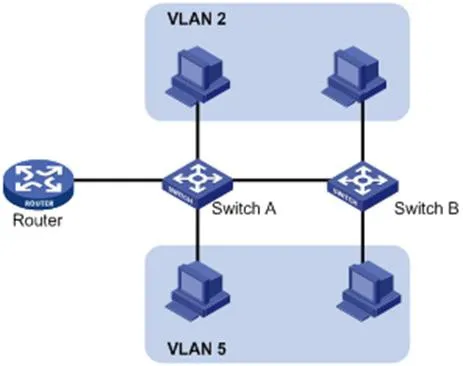
VLANs are not limited by physical location. Devices can be on the same switch, cross switches, or span routers while belonging to the same VLAN.
Advantages of VLAN:
Restrict broadcast domains, reduce routing load, lower latency, save bandwidth, and improve performance.
Enhance security: Layer 2 isolation between VLANs. Communication requires Layer 3 routing.
Flexible virtual workgroups: Users can be grouped logically without physical cabling changes.
To identify VLAN frames, a VLAN tag is added to the Ethernet header at the data link layer (Layer 2).
IEEE standardized VLAN tagging with the 802.1Q protocol in 1999. It defines a standard method for tagging Ethernet packets with VLAN information.
802.1Q inserts a 4-byte tag between the source MAC address and the EtherType field:
2 bytes: TPID (Tag Protocol Identifier)
2 bytes: TCI (Tag Control Information)
TCI includes PCP (Priority Code Point), CFI (Canonical Format Indicator), and VID (VLAN ID).

Figure 1-2 Traditional Ethernet Frame Format
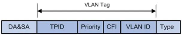
Figure 1-3 VLAN Tag Fields
VLAN Tag Fields:
TPID: 16 bits, indicates 802.1Q tag; default value 0x8100.
Priority: 3 bits, 802.1p Class of Service (CoS).
CFI: 1 bit, MAC address format; 0 = standard, default value 0.
VLAN ID: 12 bits, identifies VLAN; valid range 1–4094 (0 and 4095 reserved).
Note: For double-tagged (QinQ) frames, the switch processes only the outer tag; inner tags are treated as payload.
LLDP (Link Layer Discovery Protocol) allows devices to advertise and receive neighbor information over the local network. Information is stored in MIBs and can be queried via SNMP (RFC 2922).
LLDP uses TLV (Type/Length/Value) structures to carry device information. Multiple TLVs form an LLDPDU (LLDP Data Unit).
| Type | Length | Value |
| 7 bits | 9 bits | 0-511 bytes |
Figure 1-4 TLV Structure
LLDP-MED (Media Endpoint Discovery) is an extension for VoIP devices, providing:
Capability discovery
Voice VLAN configuration
PoE power management
Inventory management
Location identification for emergency calls
Note: LLDP and LLDP-MED cannot run simultaneously on the same port.
LLDP Functions on IP Phones:
When LLDP is enabled, the phone periodically advertises itself and listens to the switch. If the Application Type = Voice, the phone automatically learns the Voice VLAN ID from the switch, updates its configuration, and reboots to apply the VLAN.
LLDP Configuration Steps (Web UI):
Log in to the web UI as admin/admin.
Go to Network → Advanced.
Enable LLDP.
Set the transmit interval (1–3600s).
Click Apply and reboot the phone.
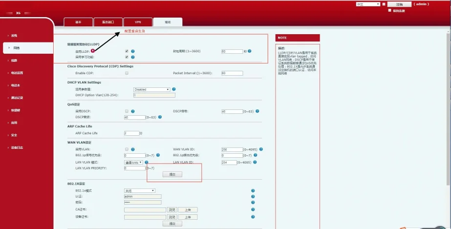
Figure 1-5 LLDP Configuration Interface
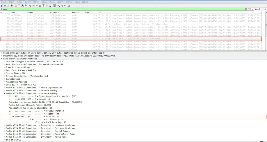
After enabling LLDP, the phone:
Periodically sends multicast LLDP packets.
Accepts LLDP packets on the WAN/LAN port.
Supports MAC/PHY configuration.
Obtains VLAN from Network Policy TLV (overrides manual settings).

CDP (Cisco Discovery Protocol) is a Cisco proprietary layer 2 protocol for device discovery.
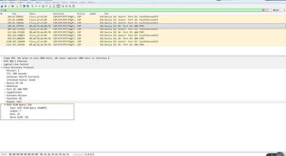
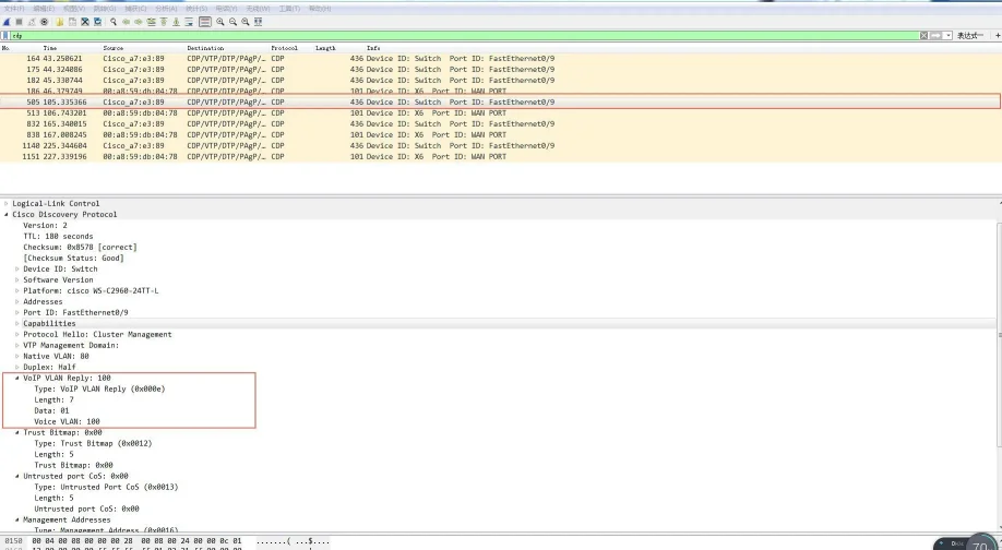
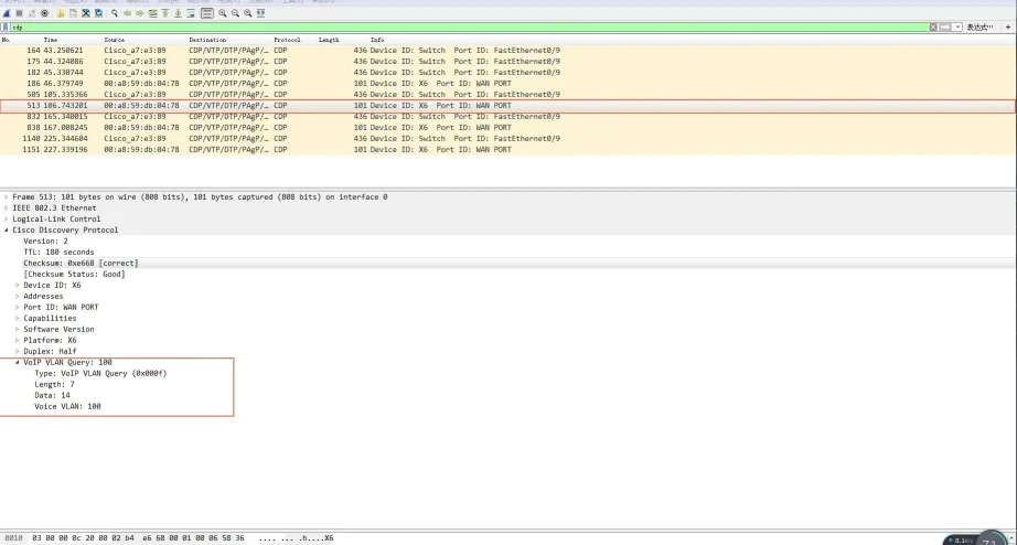
CDP Functions on IP Phones:
The phone advertises itself and listens to CDP packets from the switch. It automatically learns the Voice VLAN ID, updates configuration, and reboots.
CDP Configuration Steps (Web UI):
Log in as admin/admin.
Go to Network → Advanced.
Enable CDP.
Set the message interval (1–3600s).
Click Apply.
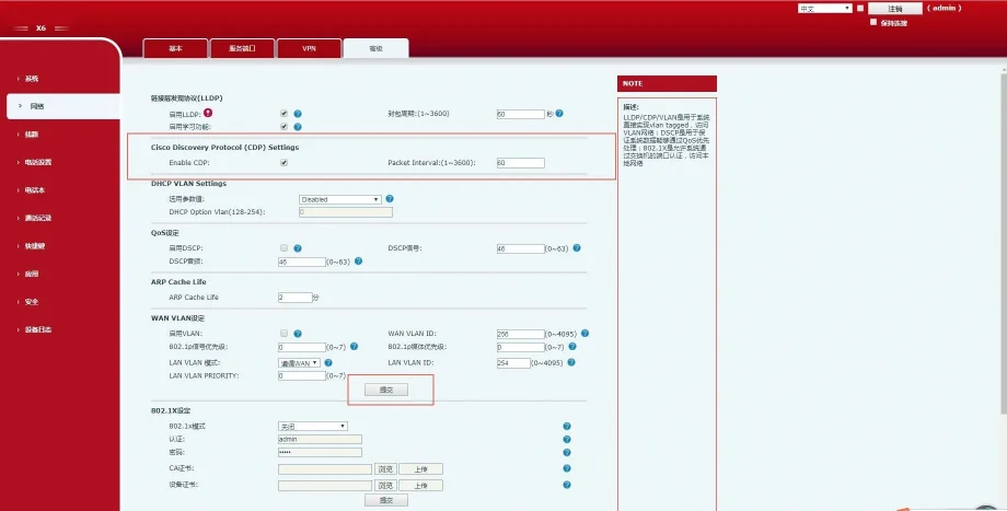
Figure 1-6 CDP Configuration Interface
The phone supports VLAN discovery via DHCP. By default, it uses Option 132 to obtain the VLAN ID. Up to 5 custom DHCP options are supported.
DHCP VLAN Configuration Steps (Web UI):
Log in as admin/admin.
Go to Network → Advanced.
Enable DHCP VLAN.
Enter DHCP Option numbers (e.g., 132).
Click Apply.
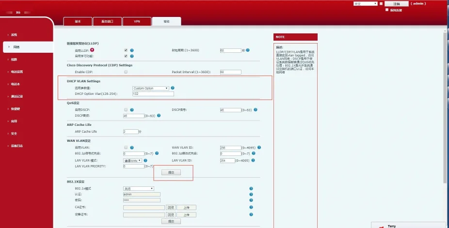
Figure 1-7 DHCP VLAN Configuration Interface
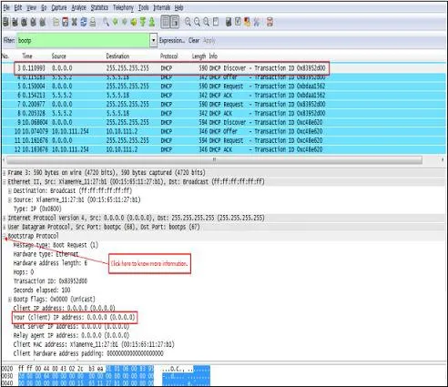
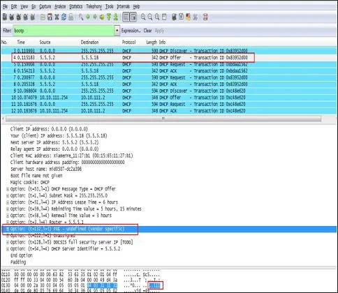
Operation Flow:
Phone broadcasts DHCP Discover.
Server replies with Option 132 (VLAN ID).
Phone releases the current IP, tags all traffic with the learned VLAN ID, and performs DHCP again.
VLAN is disabled by default. You can configure VLAN for the WAN (Internet) port and LAN (PC) port separately with VLAN ID and 802.1p priority (0–7, 7 highest).
WAN VLAN Configuration (Web UI):
Log in as admin/admin.
Go to Network → Advanced.
Enable VLAN.
Set WAN VLAN ID (1–4094).
Set Priority (0–7).
Click Apply.
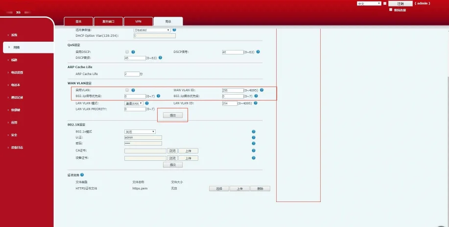
Figure 1-8 WAN VLAN Configuration
LAN VLAN Configuration (Web UI):
Log in as admin/admin.
Go to Network → Advanced.
Set LAN VLAN Mode and ID.
Set Priority.
Click Apply.
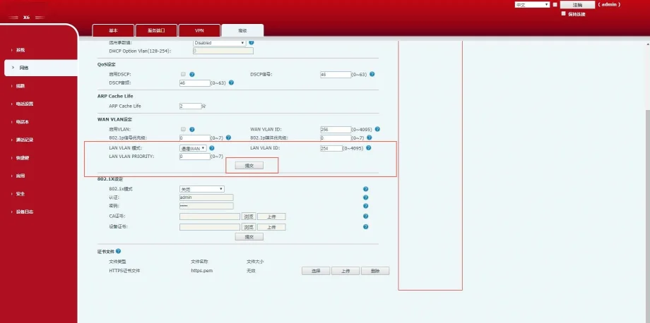
Figure 1-9 LAN VLAN Configuration
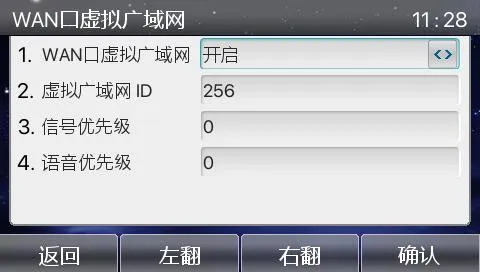
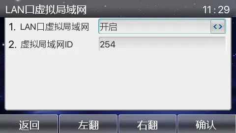
Phone LCD VLAN Configuration:
Menu → Advanced (Password:123) → Network → QoS&Vlan → WAN VLAN / LAN VLAN
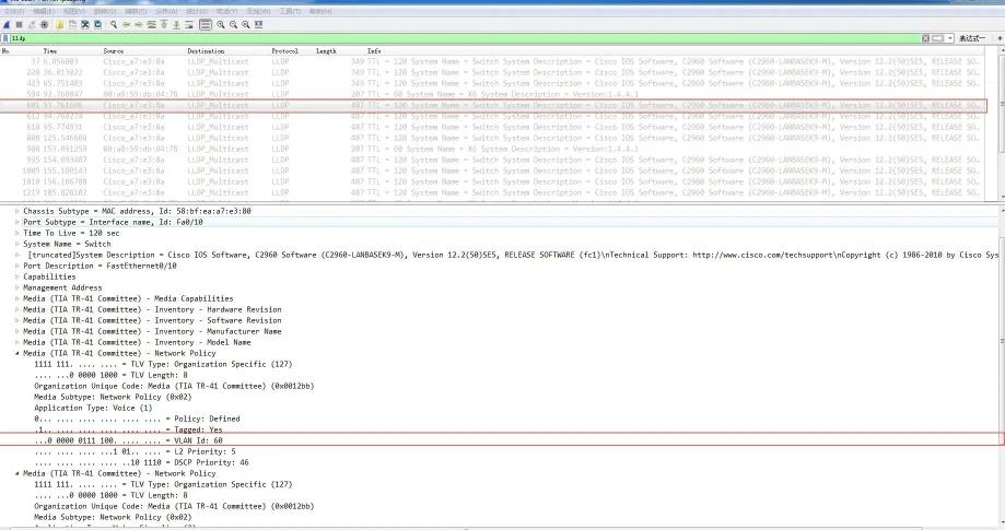
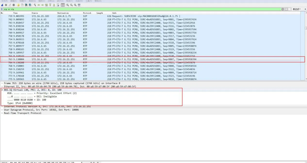
Configuration Verification:
Capture packets to verify 802.1Q tags, VLAN ID, and 802.1p priority in SIP and RTP frames.

Ethernet switch ports support three modes:
Access: Belongs to 1 VLAN; used for endpoints (PCs).
Trunk: Carries multiple VLANs; used for switch interconnections.
Hybrid: Carries multiple VLANs; supports custom untagged egress.
Key Rules:
Tagged: Frames retain the 802.1Q VLAN tag when sent.
Untagged: The switch removes the VLAN tag before sending.
PVID (Port VLAN ID): The default VLAN assigned to untagged incoming frames.
| Port Type | Ingress Processing | Egress Processing | |
| Untagged Frame Received | Tagged Frame Received | ||
| Access | Add PVID tag | Drop if VLAN != PVID | Remove tag and forward |
| Trunk | Add PVID tag if allowed | Accept if VLAN allowed | Remove tag only if VLAN = PVID |
| Hybrid | Add PVID tag if allowed | Accept if VLAN allowed | Tag or untag based on port configuration |
| Parameter | Default | Range |
| VLAN ID | 1 | 1–4094 |
| VLAN Name | VLANxxxx | — |
| MTU | 1500 | 1500–18190 |
| Status | Active | Active/Suspended |
| Step | Command | Purpose |
| 1 | configure terminal | Enter global config mode |
| 2 | vlan | Create or edit VLAN |
| 3 | name | Set VLAN name |
| 4 | end | Exit to privileged mode |
| 5 | show vlan | Verify configuration |
| 6 | copy running-config startup-config | Save config |
| Step | Command | Purpose |
| 1 | configure terminal | Enter global config |
| 2 | no vlan | Delete the VLAN |
| 3 | end | Exit |
| 4 | show vlan brief | Verify deletion |
| Step | Command | Purpose |
| 1 | configure terminal | Global config |
| 2 | interface | Select port |
| 3 | switchport mode access | Set as access port |
| 4 | switchport access vlan | Assign VLAN |
| 5 | end | Exit |
| Step | Command | Purpose |
| 1 | configure terminal | Global config |
| 2 | interface | Select port |
| 3 | switchport mode trunk | Set as trunk |
| 4 | switchport trunk native vlan | Set native VLAN |
| 5 | end | Exit |
switchport trunk allowed vlan { add | all | except | remove }
switchport trunk native vlan
Cisco 2960 Series Switches