
IntroductionOverviewThis document mainly introduces the Remote DTMF Trigger func
This document mainly introduces the Remote DTMF Trigger function for intercom products.
All intercom devices support remote DTMF triggering of output ports. This feature is simple and practical, and it can remotely trigger the intercom output port for applications such as remote door unlocking and remote barrier gate opening. It can help customers build more unattended solutions, such as communication systems for unattended parking lots, unmanned internet cafés, unattended gyms, and similar sites.
All company intercom products, including BPA2, BPA2S, Bi10, Bi10S, Bi10V, Bi10SV, Bi10D, Bi10SD, Bi16V, Bi12, Bi16S, Bi16SV, and Bi18S.
Remote DTMF triggering can work in two ways:
One method is that when a visitor or vehicle owner needs to open a barrier gate or unlock a door, they press the help button on the intercom. After the service desk staff answers the call and confirms the visitor’s or driver’s location and situation, they only need to press a trigger code on the phone, and the intercom will activate the output port to open the door or barrier gate.
The other method is that the service desk staff calls the intercom. After the intercom answers automatically, the staff enters the trigger code, and the intercom will activate the output port to open the door or barrier gate. The workflows of these two methods are shown below:
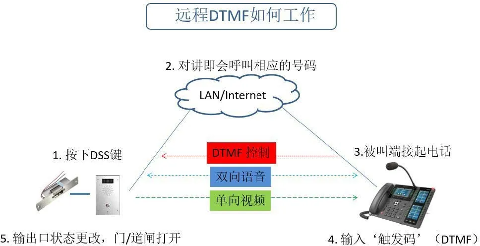
(i16V - Caller Mode)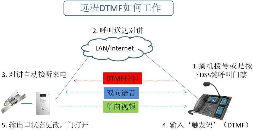
(i16V - Callee Mode)

① Before you begin, make sure the intercom is connected correctly to the barrier gate or electric lock;
② Prepare one configuration PC, and connect the PC, phone, and intercom device to the same local area network, ensuring that the network between the PC and the devices is reachable.
Using an Bi16V connected to an electric lock, an IP phone, and a PC as an example, the basic network connection is shown below: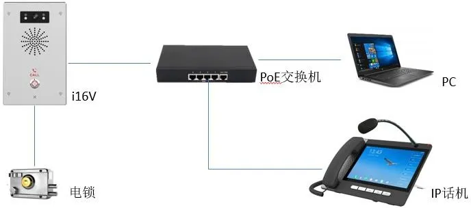
Before using the Remote DTMF Trigger function, configuration is required on both the intercom and the phone. In this section, the i16V and A32i are used as examples to explain the configuration of the Remote DTMF Trigger function.
By default, each intercom output port has a unique DTMF trigger code assigned at the factory. Before using the Remote DTMF Trigger function, users need to confirm that Remote DTMF Trigger is enabled. The trigger code can also be changed if required. The configuration steps are as follows:
1) Log in to the intercom web interface;
2) Go to the Security Settings page;
3) Under Alarm Trigger Settings → Output 1/2, enable the Remote DTMF Trigger function;
4) Modify the corresponding DTMF trigger code as needed;
5) Click Submit to save the changes;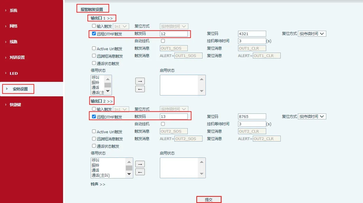
When the phone is in a call with the i16V intercom, the user can enter the trigger code from the phone keypad to open the barrier or door. A DSS key can also be configured so that once the call is established, the user can directly press the DSS key to trigger the i16V output port. The configuration steps are as follows:
1) Log in to the phone web interface;
2) Go to Function Key → Function Key;
3) Select a function key, set its type to DTMF, and enter the trigger code of the i16V in the Value field;
4) Click Submit to save the changes;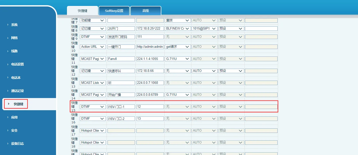
Note: The value configured on the phone must be the same as the trigger code configured on the intercom.
In actual use, users may encounter failures with Remote DTMF Trigger. This can be caused by incorrect wiring, improper configuration, transmission errors, network problems, and other issues. The troubleshooting steps are as follows:
1) Check the wiring
Check the connection between the i16V and the electric lock / barrier gate / alarm light, and confirm that the external device is correctly connected to the i16V output port;
2) Confirm the output connection
Use other output trigger methods, such as input trigger, Active URI trigger, or call status trigger, to see whether the i16V output port can be triggered normally. If not, return to Step 1) and check the wiring again. If other trigger methods work normally but Remote DTMF Trigger still does not work, continue with the following checks;
3) Check the configuration
Check the intercom settings and confirm that Remote DTMF Trigger is enabled and that a trigger code has been configured. Confirm that the correct trigger code is entered on the phone side. If a function key is used, check that the function key is configured correctly and that its value matches the trigger code configured on the intercom;
4) Check the DTMF type
The intercom supports DTMF triggering using SIP Info or RFC2833. Confirm that the DTMF type used on the phone side is set to SIP Info or RFC2833:
① If the call is made through a SIP server, go to Line → SIP Page, and set the DTMF type to RFC2833;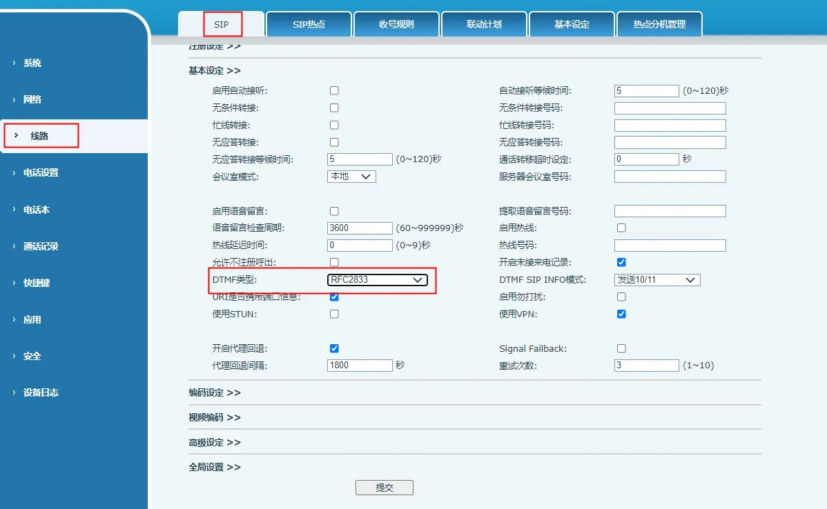
② If it is an IP call, go to Line → Basic Settings, and set the DTMF type to RFC2833;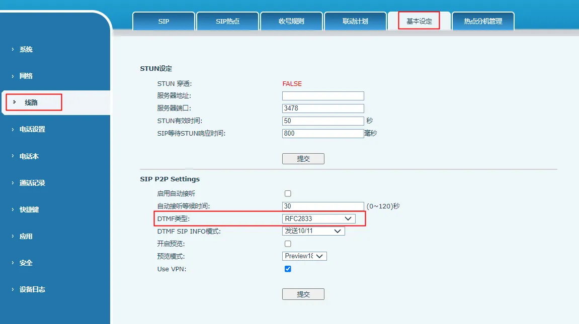
5) Capture packets for analysis
If the problem still exists after the checks above, capture a packet trace from the intercom, the phone, and the server (if the call is made through a server), and provide the files to technical support for analysis. The capture steps are as follows:
① On both the intercom and the phone, go to System → Tools and start web packet capture;
② Use the intercom and the phone to repeat the Remote DTMF Trigger operation and reproduce the issue;
③ Stop the web packet capture and provide the saved files to technical support;
Note: If the call is made through a SIP server, please also capture a packet trace on the server side. Packet capture procedures vary by server vendor, so consult the SIP server supplier for details.```