This guide explains IP direct dialing for access control devices on the same LAN without PBX registration, covering supported models, network connection, shortcut calling, manual dialing, dial peer rules, keypad settings, and unregistered outbound calling.
When access control devices are in the same interconnected LAN and are not registered to a PBX environment, the IP direct dialing function can be used to enable internal communication between devices.
BHP-SOS10/BHP-SOS10V/BHP-SOS10D/BHP-SOS12/BHP-SOS16/BHP-SOS16V/i18S/i20S/i23S/i30/i31S/ i32V/i33V/i33VF/i61/i62/i63/i64
① One i20S and one phone (X7A), one POE switch (or DC power supply), and connect the devices to the switch.
② One debugging computer, and connect the computer to the switch to ensure that the network between the computer and the phone is reachable.
Connect the i20S/i52W/i53W to the switch, and connect the computer to the same switch as the device. Ensure that the network between the computer and the device can communicate with each other. The connection diagram is shown below: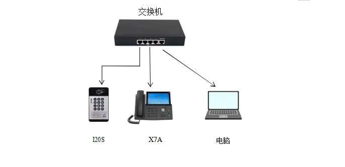
Device and computer connection diagram
BHP-SOS10/BHP-SOS10V/BHP-SOS10D/BHP-SOS12/BHP-SOS16/BHP-SOS16V/i18S/i32V/i33V/i33VF/i61/i62/i63/i64
i64: In standby mode, press and hold the speed dial key for 10 seconds. A beep will continue for 5 seconds. Press the speed dial key once within 5 seconds, and the beep stops, then the device automatically reports the IP address.
i20S/i23S/i30/i31S: Press and hold the # key on the device for 3 seconds within 30 seconds after power-on. The device will automatically announce its local IP address by voice.
Log in to the device web backend. In Shortcut Key---Shortcut Key---Shortcut Key Settings, fill in the information and submit. Select “Memory Key” as the type, customize the name, enter the peer device IP as the value, and select “Speed Dial” as the type.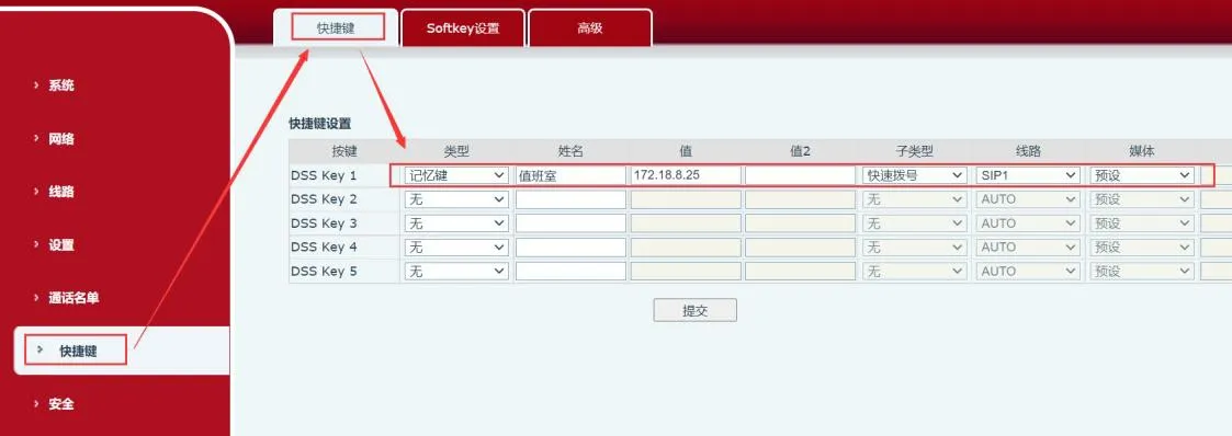
Applicable to: i20S/i23S/i30/i31S/i32V/i33V/i33VF/i64
Enter the IP address on the access control keypad to make a call. For example, 172.18.8.23 calls 172.18.8.5, where “.” is replaced by the “*” key.
To use dialing rules, configuration is required on the device web page. The following section describes the steps for configuring dialing rules in detail.
Log in to the web page: enter the obtained IP address in the browser, then enter the username and password to log in. The default username and password are admin.
After logging in to the web page, go to “Line”---“Dial Peer”---“Add Dial Peer”, and configure it as shown below:
① Number: custom. The number entered here will be used instead of the original number for calling;
② Destination: the destination is the address to be called. You can enter an IP address or SIP account. If a SIP account is used, SIP account registration is required. This example uses an IP address;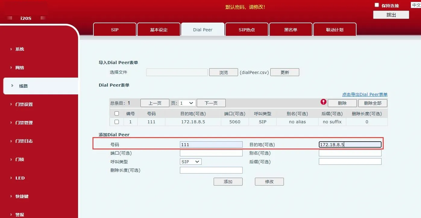 Add dial rule diagram
1. In “Access Control Settings”---“Function Settings”, configure the following as shown in the figure. In “General Settings”, make the following settings:
① Set “Key Mode” to “Dialing and Password Input”: this means key input can be used for dialing and password input;
② Set “Default Input Mode” to “Password”: this means key input is used only for password verification by default;
In “Programmable Key Settings”, make the following settings:
Set the standby status of “Key *” to “Input Mode Switch”, and set “Dial” to “Outgoing Number”;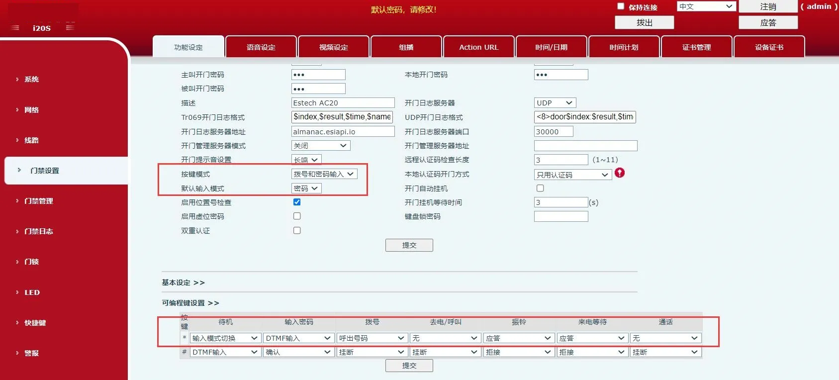 Key mode and programmable key setting diagram
2. In “Access Control Settings”---“Function Settings”---“Basic Settings”, uncheck “Fixed Length Dialing”, as shown below;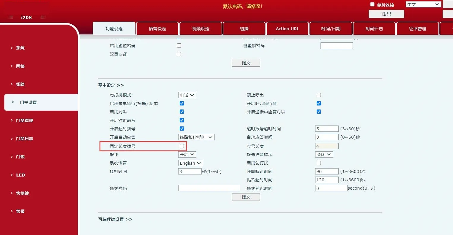
Cancel fixed length dialing setting diagram
3. After completing the above configuration, enter “*custom number*” on the device keypad to call out immediately. You can also enter “*custom number” and wait 3 seconds for the device to call out automatically. In this example, enter “*111*” or “*111” to call out.
Precautions:
Disable strict UA matching on the called device to ensure that the device can receive incoming calls.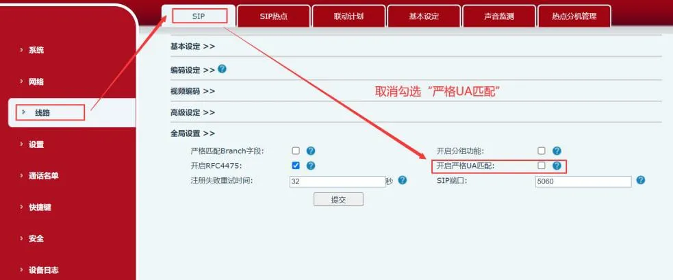
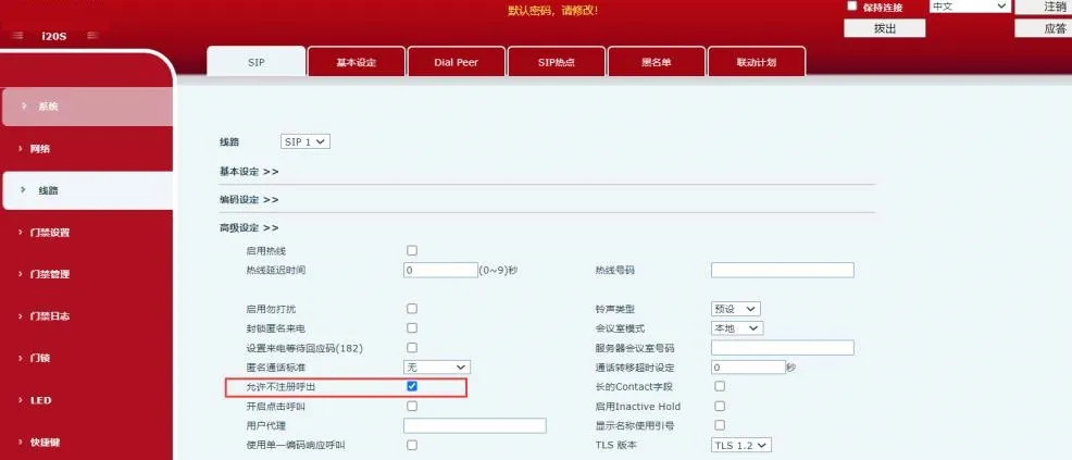
Enable unregistered outbound calling to ensure that the device can call out without registration.