
This guide details how to configure multicast for intercom and access control devices, including sender setup, auto listening, and manual listening modes with complete network and shortcut configuration steps.
The multicast function allows the sender to transmit audio and other information to a specified multicast IP address. All devices listening to this address can receive the broadcast content, similar to a public announcement system. This document provides detailed instructions for using multicast on access control and intercom devices.
All intercom and access control devices.
① One intercom or access control device (Bi30 as example), one IP phone (GP210i as example), one PoE switch (or DC power supply). Connect all devices to the switch.
② One debugging computer connected to the same switch to ensure normal network communication between the computer and devices.
Connect the Bi30 and GP210i to the switch, and connect the computer to the same switch to ensure network connectivity. The connection diagram is shown in Figure 1.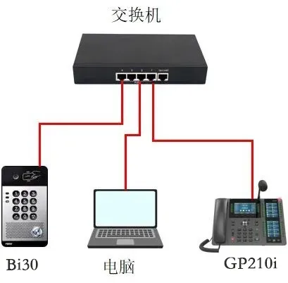
Figure 1 Device and Computer Connection Diagram
Multicast requires configuration on both the sender and listener devices. The detailed steps are as follows:
(1) Log in to the Web UI: Enter the device’s IP address in a browser, and log in with username and password (default: admin).
(2) Navigate to Shortcuts --- Shortcut Settings, and configure as shown in Figure 2:
① Type: Select Multicast;
② Number 1: Enter multicast address:port (IP range: 224.0.0.0 – 239.255.255.255, port: 1024–65535). Example: 224.0.0.1:1366. For channel usage: address:port:channel (default channel=0 if not set).
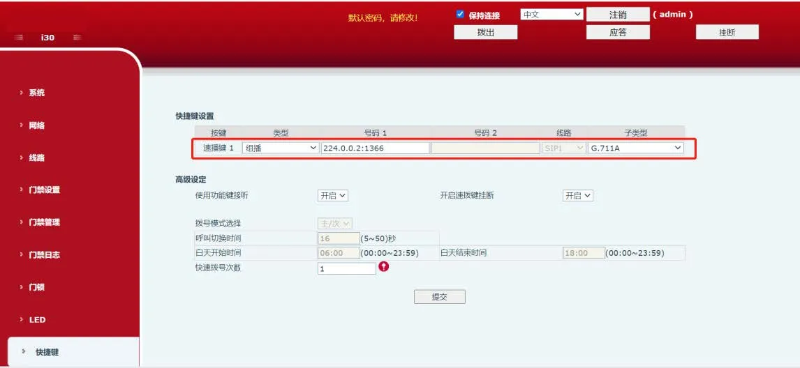
Figure 2 Multicast Sender Configuration Diagram
There are two listening modes: Auto Listening and Manual Listening. Details are provided below.
The device automatically answers multicast broadcasts. Applicable to all devices (using X210i as example).
(1) Log in to the device: Enter the IP address in a browser, log in with default admin/admin.
(2) Navigate to Phone Settings -- Multicast, configure as shown in Figure 3:
① Name: Custom label displayed on the screen during multicast;
② Host:Port: Multicast IP and port (must match sender);
③ Channel: Default 0, must match the sender’s channel value if used.
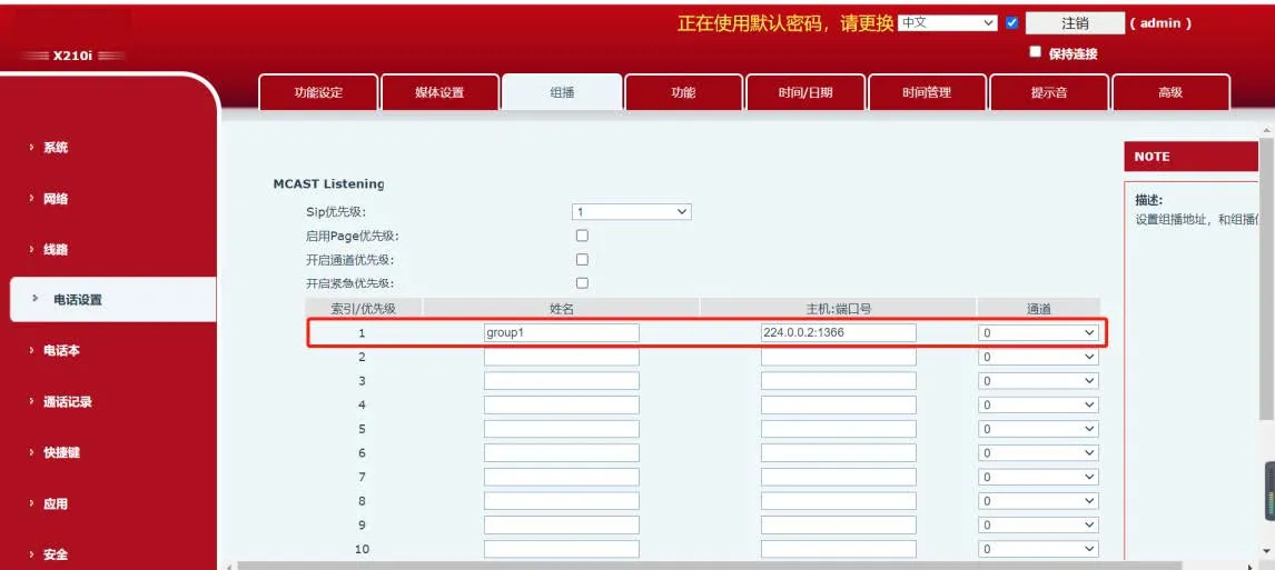
Figure 3 Auto Listening Configuration Diagram
(3) After configuration, the device will auto-answer when multicast is received and show the call interface.
The device does not answer automatically; you must press the function key to receive multicast (using X210i as example).
(1) Navigate to Shortcuts -- Shortcut Settings, configure as shown in Figure 4:
① Type: Select MCAST Listening;
② Name: Custom multicast label;
③ Value: multicast address:port (same as sender). Example: 224.0.0.1:1366. For channel: address:port:channel.
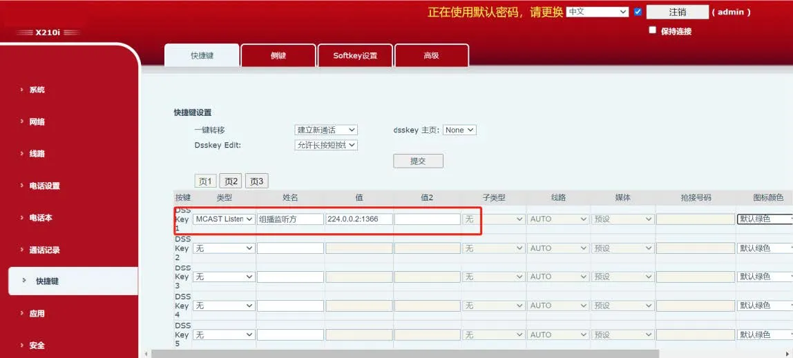
Figure 4 Manual Listening Configuration Diagram
(2) After configuration, when multicast is sent, the device key lights up green. Press the key to receive multicast (interface activates, key turns red).