
Learn how to connect an electric lock to the Bi20S and Bi30 indoor access control units, including JP1 jumper settings, internal or external power modes, lock wiring, and web-based testing.
This guide explains how to wire an electric lock to the Bi20S and Bi30 indoor access control units. The correct wiring method depends on the lock’s startup current and power requirements.
If the lock startup current is below 12V/500mA, the access control unit can power the lock directly. This is referred to as internal power mode. If the lock startup current is higher than 12V/500mA, the access control unit should be used only as a relay trigger, and the lock must be powered by its own external power supply. This is referred to as external power mode.
These two modes are selected by adjusting the JP1 jumper. Follow the instructions below to choose the correct mode and complete the wiring safely.
Bi20S, Bi30
1. One Bi20S indoor access control unit, one electric lock, one power adapter for the lock, and one PoE switch (or a DC power supply).
2. Confirmation of which power mode the lock requires, followed by the correct JP1 setting on the indoor unit.
3. One computer for setup and testing, connected to the same network as the access control device.
Connect the access control unit to the switch, then connect the computer to the same switch so both devices are on the same network and can communicate with each other, as shown in Figure 1.

Figure 1
Before wiring the lock, open the access control unit and set the JP1 jumper according to the lock power mode. Then connect the lock using the appropriate wiring method.
Use a screwdriver to remove the screws on the unit, then open the housing.
Adjust the JP1 jumper according to the lock specifications.
When the lock startup current is below 12V/500mA, the indoor unit can supply power to the lock. This is internal power mode.
When the lock startup current is above 12V/500mA, the indoor unit works only as a dry-contact control output, and the lock must use its own external power supply. This is external power mode.
JP1 Setting for Internal Power Mode

JP1 Setting for External Power Mode

Internal Power Wiring
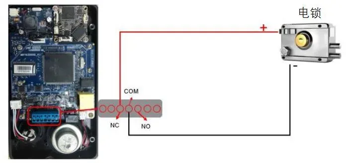
Note: Confirm whether the lock is Fail-safe (locks when powered) or Fail-secure (unlocks when powered), because the positive terminal is connected differently for each type. For a Fail-safe lock, connect the positive wire to NC. For a Fail-secure lock, connect the positive wire to NO.
Warning: In internal power mode, do not connect an additional external power supply to the lock at the same time, as this may damage the device.
External Power Wiring
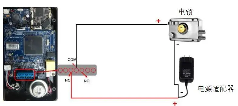
Note 1: Choose NC or NO based on the lock type.
Note 2: The relay output of the access control unit supports up to DC 30V/1A or AC 125V/0.5A.
1. If you are using external power mode, switch on the external power adapter to supply power to the lock.
2. On the setup computer, open a web browser and enter the IP address of the access control unit.

3. Enter the login credentials. The default username is admin and the default password is admin.
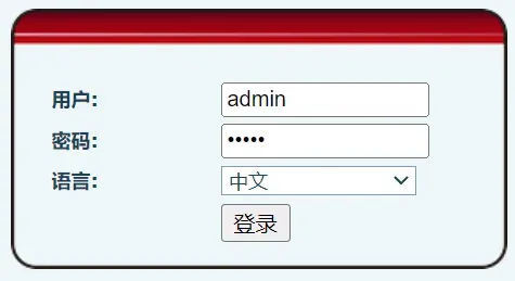
4. Go to Door Lock > Door Lock Control, then click Execute to test whether the lock opens correctly.
