
Learn how to configure dry-contact input and output on industrial intercoms, access control devices, and indoor stations for alarm triggering, linked control, DTMF activation, and server-based actions.
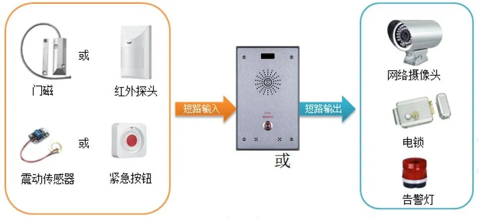
Our industrial intercoms, access control devices, and indoor stations support dry-contact input and output functions. As shown below, external devices can be connected to the intercom system to implement alarm signaling and related control actions.
This guide applies to all of our access control, intercom, and indoor station products.
① One device (the i12 is used here as the example), plus one PoE switch or DC power supply.
② One external alarm device.
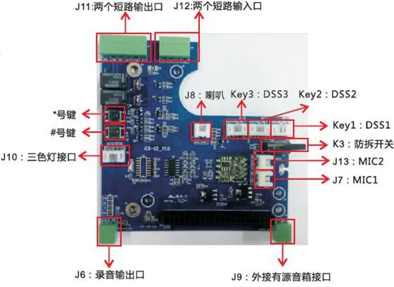
The i12 provides two groups of dry-contact input and output interfaces, labeled J11 and J12 in the diagram above. The input ports can be connected to door contacts, infrared detectors, vibration sensors, or emergency buttons to trigger preset actions. The output ports can be connected to electric locks, alarm lights, or the alarm input of a camera for linked response actions.
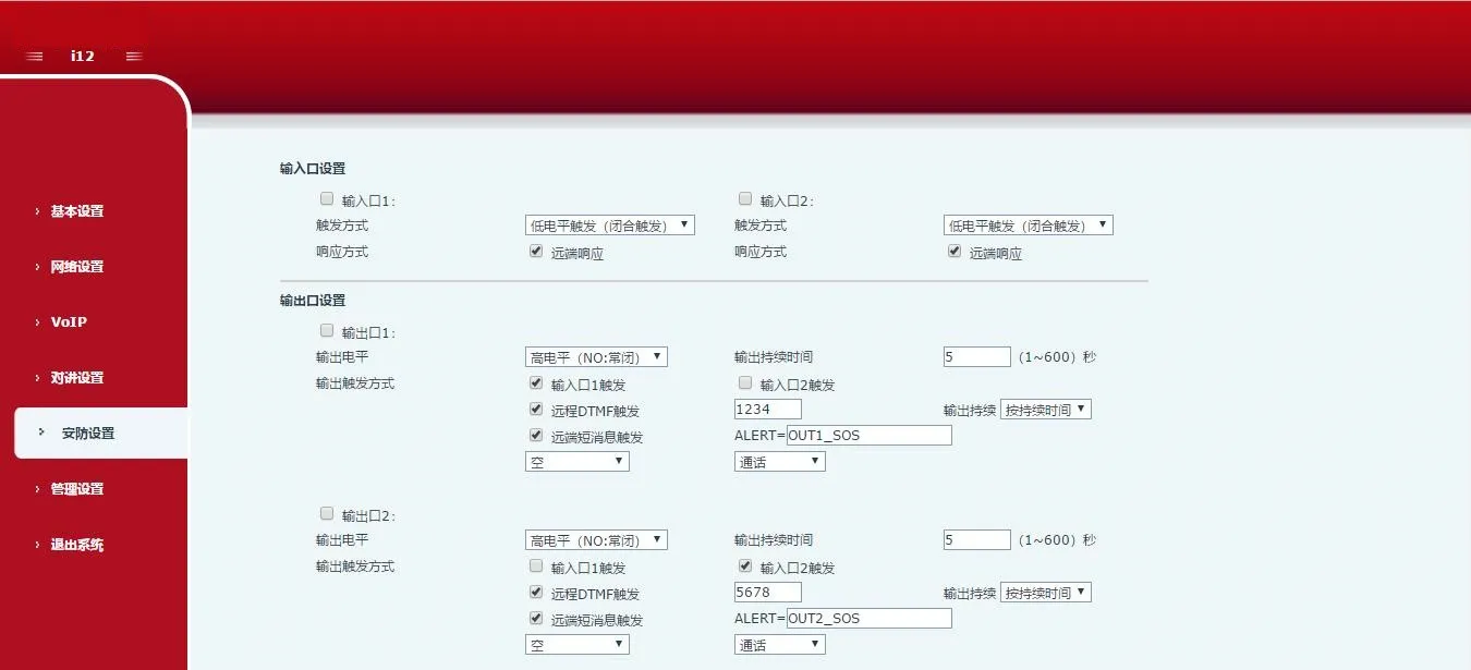
Configure the input or output settings based on the actual application requirements.
Dry-contact input ports:
Input ports can be connected to door contacts, infrared sensors, vibration detectors, or emergency call buttons to trigger preset actions.
1. Report alarms to the server by message
A user can send an SMS-style message from any compatible phone to the device. The message format is ALERT=[message]. Under the default configuration, for example, you can send ALERT=OUT1_SOS.
2. Input trigger action
When an external device is connected to the input port, the system can detect either of the following trigger modes:
High-level trigger (open-circuit trigger)
Low-level trigger (closed-circuit trigger)
Dry-contact output ports:
Output ports can be connected to electric locks, alarm lights, or the alarm input of a camera to trigger preset actions.
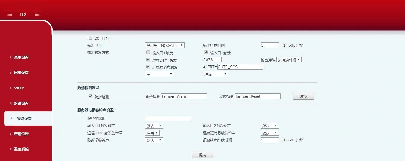
1. Trigger output by server message
The device can receive an output control message from the server and activate the corresponding output port. On the web page, enable the remote SMS trigger option. When the device receives a message in the format ALERT=[message], the configured output action will be triggered.
2. Link output to an input port
The output port can be linked to an input port so that an input event activates the output automatically. On the web page, enable the input trigger option and assign the required logical input.
3. Trigger output by remote DTMF command
The device can receive a DTMF code during a call and, after the code is verified, trigger the output port. On the web page, enable remote DTMF trigger. In the example shown, the default trigger code is 1234. During a call between the device and a phone, entering 1234 changes the output port state. After entering the DTMF code, press # to trigger the output immediately.
4. Link output to call status
The output action can also be tied to a call state. After a specific state is selected, the device starts the alarm when that call state begins, and stops the alarm automatically when the state ends.