This guide explains how an access control device connects to an electric lock, covering Fail-safe and Fail-secure locks, internal and external power modes, JP1 jumper settings, current requirements, wiring precautions, and connection diagrams.
This document explains how an access control device connects to an electric lock. When the startup current of the electric lock is less than 12V/500mA, the lock can be powered by the access control device. This is called internal power supply mode. When the startup current of the electric lock exceeds 12V/500mA, the access control device only works as a short-circuit output control, and the power must be supplied by the electric lock itself or an external power supply. This is called external power supply mode. These two modes are controlled by jumper JP1. For the specific connection method, refer to the operation instructions in this document.
Access control series
This document is intended for all users who use the access control device to connect an electric lock.
Fail-safe: electric lock that unlocks when power is off and locks when power is on
Fail-secure: electric lock that remains locked when power is off and unlocks when power is on
Fail-safe lock: when power is interrupted or a fault occurs, a fail-safe electric lock automatically unlocks so that people can leave a dangerous area. This is why they are called “safe”: they are safe for people, not for the protected space.
Fail-safe locks are usually used at entrances and exits, such as office doors or lobby doors.

Fail-secure lock: when power is off, a Fail-secure lock remains locked.
Fail-secure locks are used in access control scenarios with higher property protection requirements, such as vaults and IT rooms. They can also be used on fire doors or stair doors. In case of fire, these doors remain closed to seal part of the space and help prevent the fire from spreading.
Becke access control and video devices support both internal power supply and external power supply modes. The default device mode is external power supply mode.
Internal power supply mode: when the startup current of the electronic lock is less than 12V / 500mA, internal power supply mode can be used, and the lock interface provides 12V DC output.
External power supply mode: when the startup current of the electronic lock exceeds 12V / 500mA, external drive mode is required, and the lock interface is used as a short-circuit output control.
Note:
1) The 500mA value here includes instantaneous startup current. In general, instantaneous startup current is higher than normal operating current. If an electric lock greater than 500mA is connected, the device may restart when attempting to unlock. This is caused by overcurrent protection.
2) In internal power supply mode, the electric lock must not be connected to an external power supply. If connected incorrectly, the output relay may be burned out.

Before connection, please note:
1) Confirm the electric lock type: fail-safe or fail-secure
2) Confirm the electric lock specifications and whether the startup current is less than 12V / 500mA;
3) Start the connection
Step1. Check the electric lock specifications and make sure the working voltage of the lock is 12V and the maximum current is 500mA.
Step2. Check whether the electric lock type is fail-secure or fail-safe. If it is neither, internal power supply mode cannot be used.
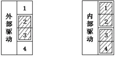
Step3. Confirm that the JP1 jumper module is connected. Connect pin1 and pin2, and connect pin3 and pin4.
Step4. According to the lock type, connect the electric lock to the COM-NC or COM-NO interface of the access control device.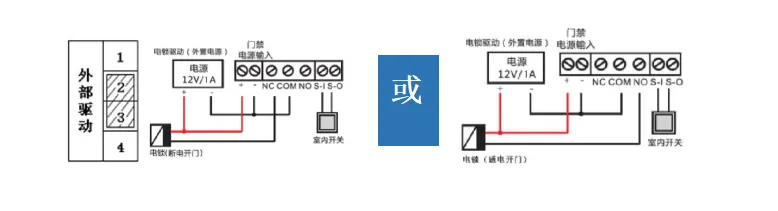
Advantages of internal power supply mode:
The installation position is usually near a door with limited interfaces, and internal power supply mode does not require an external power supply. With this method, installation is easier and cost is lower.
Note: i33V / i32V only support internal power supply mode on short-circuit output port 1.
Step1. Check the electric lock specifications and make sure the maximum voltage and current of the lock meet the relay specifications of the access control device.
Step2. Confirm the JP1 connection. Connect pin2 and pin3, and leave pin1 and pin4 empty.
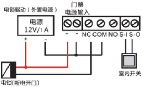
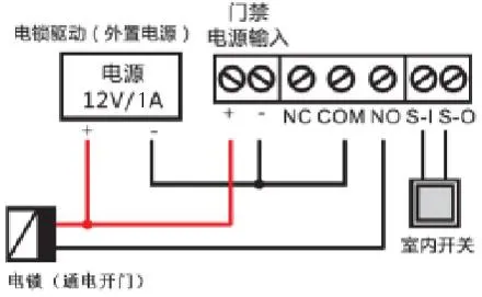
Step3. When passive mode is used, NC-COM / NO-COM works as an ON / OFF switch between the lock and the external power supply.
1) Connect the positive terminal of the external power supply to the positive terminal of the electronic lock;
2) Connect the negative terminal of the external power supply to the COM port of the access control device
3) According to the lock type, connect the negative terminal of the electronic lock to the NC or NO port of the access control device.